SCORPIO 38’ - 45’ - PARTS AND COMPONENTS DESCRIPTION - Telescopic arm
Version 1.02 May 27, 2022
20
2.4 TELESCOPIC ARM
The arm of the crane is made up of different sections that extends or retracts automatically controlled
by an operator with the Hand Command. In this chapter we will focus on the arm itself, the mechanics
in it and how to strap it safely.
To mount the arm into the fulcrum it
needs to be lifted using two forklifts or
similar devices that can lift the arm
and insert it into the fulcrum using the
guiding pin as a reference in order to
assemble it properly. From the factory
is shipped inside a box with 2 straps
marking the lift point for future
references.
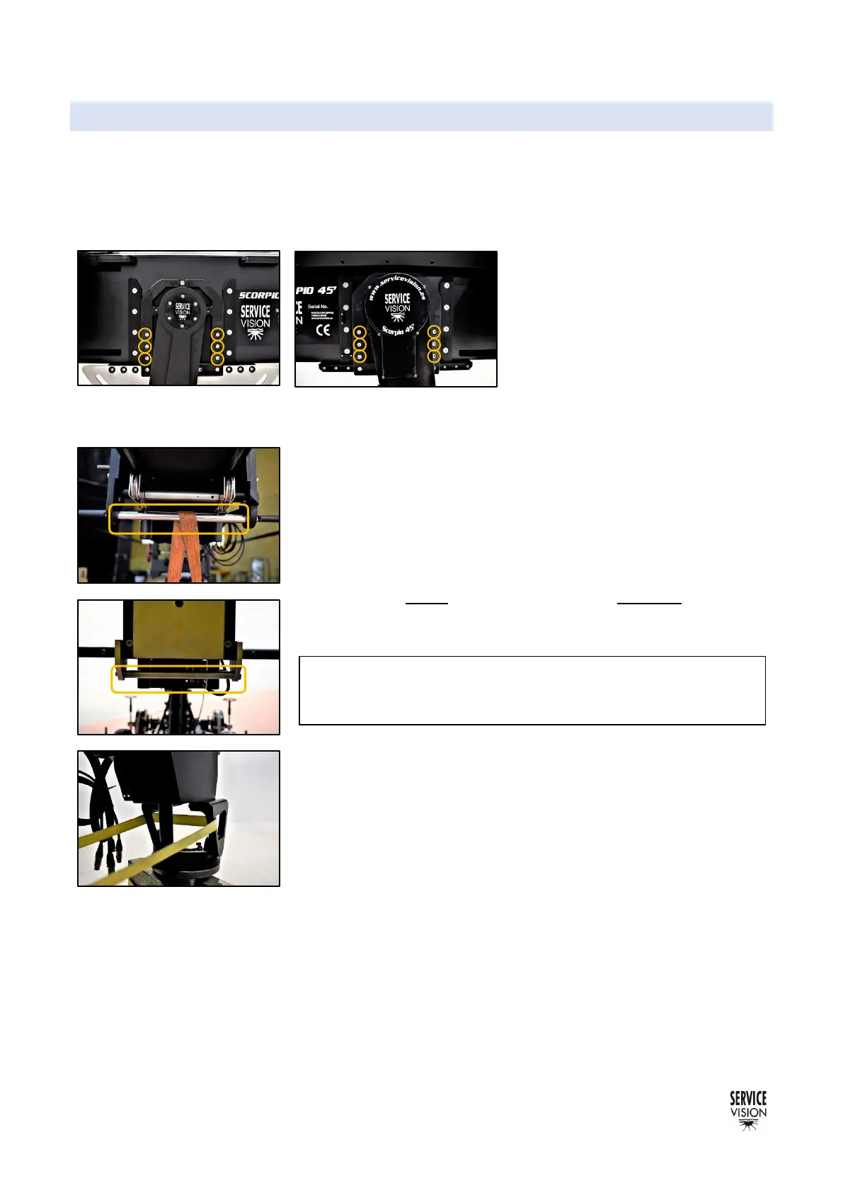
When the arm is slipped into the fulcrum, the side screws (DIN912
M10x20mm) needs to be tightened equally in both sides of the crane,
other ways there might be problems on the telescopic movement.
Once assembled, the arm must always be strapped to the dolly base
rings via the adjustable ratchet straps provided with the crane. The
strapping points are shown in the fig. 2.43, 2.44, 2.45. Notice that
when the arm is empty is always heavier in the back part of the arm.
Always use two straps in the front and one in the back.
The strap from the leveling head is to prevent that the telescopic
sections extend while it is being transported. The strap in the leveling
head needs to be used as shown in fig. 02.45 in order to do not
damage the mechanism in the leveling head. Never strap it in the
movable part of the leveling head.
The arm of the SCORPIO cranes is made up of a main section, fixed,
and four telescopic sections. These tubes are made by extrusion from
one block of aluminum and give to the crane the rigidity needed to
perform movements of the camera from 2.26m/7’5’’ with the arm fully
closed to 14m./45’11’’ in the maximum length.