SCORPIO 38’ - 45’ - PARTS AND COMPONENTS DESCRIPTION - Telescopic arm
Version 1.02 May 27, 2022
SERVICEVISION BIS SL
Ríos Rosas, 20 · 08940 CORNELLA DE LLOBREGAT (Barcelona) Spain · Tel. 34 93 223 86 30 · Fax 34 93 223 86 31 21
comercial@servicevision.es · www.servicevision.es
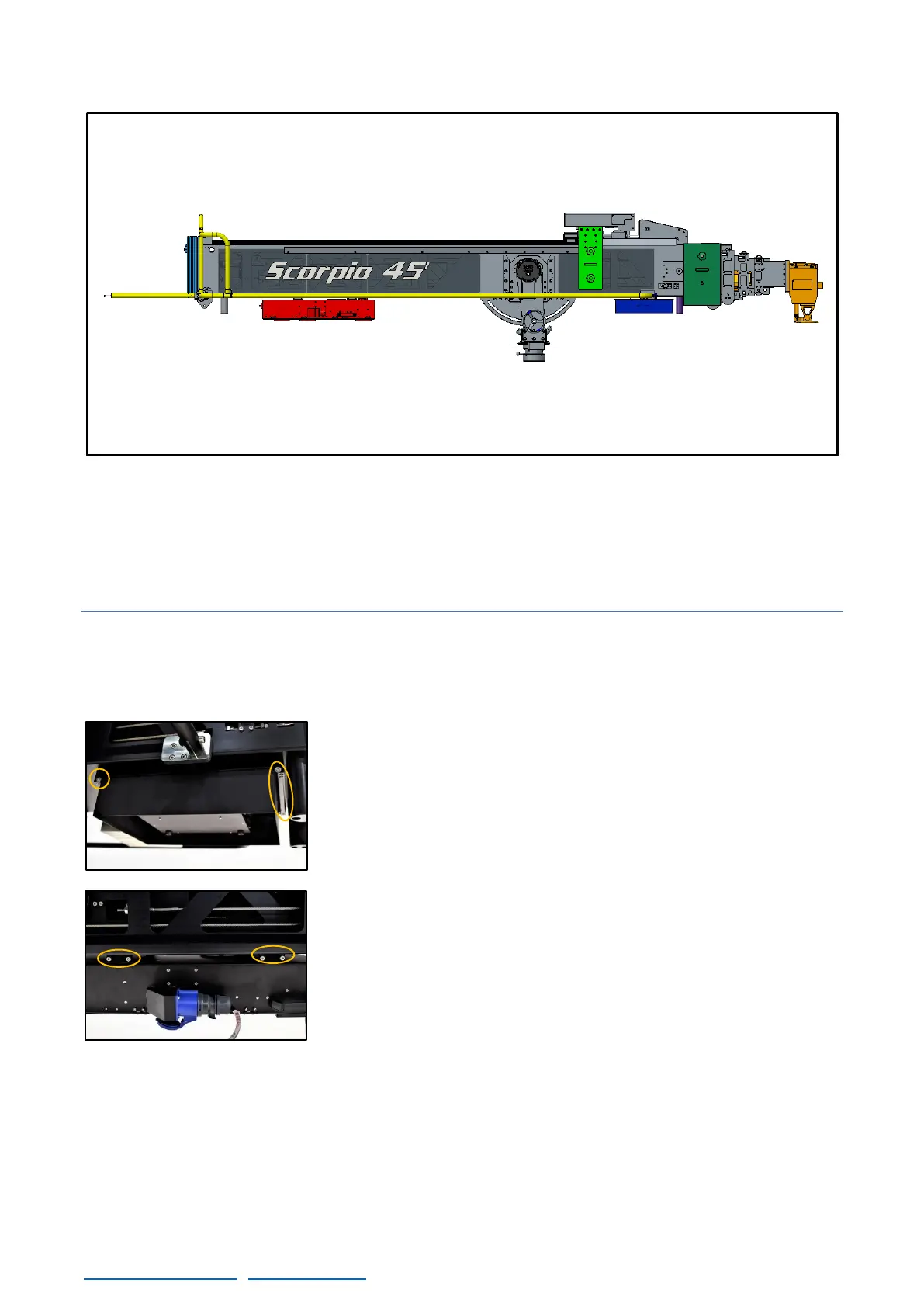
The basic components of the telescopic arm are the dynamic counterweight carriage (flashed in light
green), the levelling head (orange), the electronic box (red) which controls the system, the power unit
for the Scorpio Heads (blue), the protection bars (yellow) and the counterweight supports (front in
dark green and rear in light blue).
2.4.1 MAIN SECTION
The Main section is the fix part that holds the rest of the components detailed before. Underneath
of it there are 4 support legs to rest the arm in case the electronic box and the power unit for the
Scorpio Heads are not mounted.
There are 2 guiding supports, in front and in the back of the crane to
hold the Power Unit for Scorpio Heads and the Electronic Box from
the crane. To mount the Power Unit, remove the stopper screws from
the guides and slide it in with the XLR connectors facing the front of
the crane.
To mount the electronic box, remove the covers from the sliding
guides (fig. 2.48) and slide the EB with the main AC connector in the
right side of the crane. Do not do this operation alone, the Electronic
Box is heavy (over 50kg).