2. Design and method of operation
10
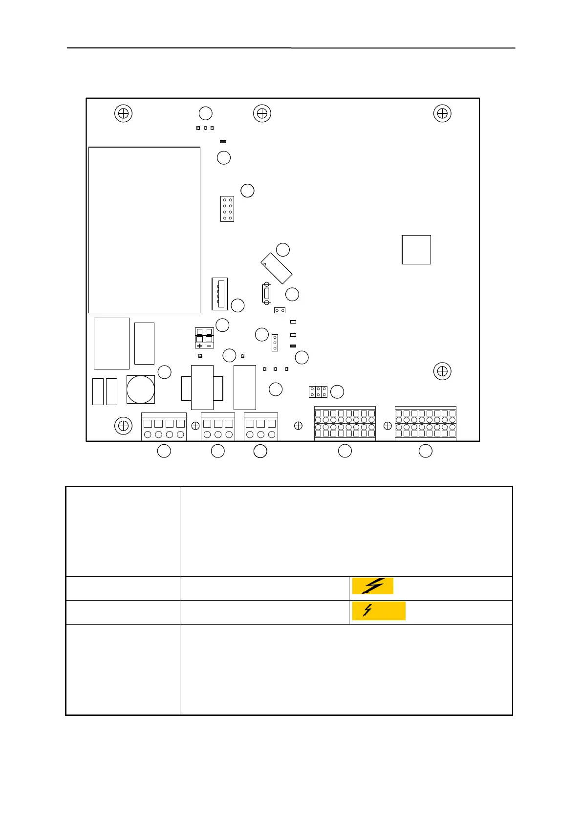
2.2.3 PRIMUS+ / IO electronics board
Connectors and termi-
nals:
(1) "Mains/Option" L/N: Control unit power supply
O1/O2: Optional 24V module power supply
(2) "Relay metal" Potential free change over contact
(3) "Relay fault" Potential free change over contact
(4) "Switching outputs" J5, connector, magnetic valves, signal combi., etc.
(5) "Switching inputs" J6, connector, sensors, switches, etc.
(12) "MV voltage external" J13, connector 24V external (option)
(18) "CU connection" J10, plug connection to CU electronics
Elements connected to
mains voltage:
(1) "Connector, Mains/Option"
(10) "Mains fuses
Elements connected to
external voltage:
(2) "Connector, relay metal"
(3) "Connector, relay fault"
(7) "Monitor LED, MV1-3" LD 10, magnetic valve (MV1)
LD 9, magnetic valve (MV2)
LD 8, magnetic valve (MV3)
(9) "Monitor LED, relay" LD 11, relay fault (84, 81, 82)
LD 12, relay metal (74, 71, 72)
(17) "Monitor LED, Vcc” LD 1, +24V
LD 2, +10V
LD 3, +3.3V
9
25 26 27 28 29 30 31 32
1
17 18 19 20 21 22 23 24
10
2
11
3
12
4
13
5
14
6
15
7
16
8
8171N 8474L 8272O1 O2
TP2
JP9
F1
JP10
LD10
LD9
LD8
LD11
LD12
J8
J10
J14
J13
LD1
LD2
LD3
TP1
1
J5 J6
JP3
3
2
1
3
8
1
4
6
2
5
7
J11
11 3 5
2 4 6
2
3
4
5
6
7
8
9
14
13
3
11
15
(GND)
(GND_24V)
2
17
10
16
12
18