5. Commissioning
22
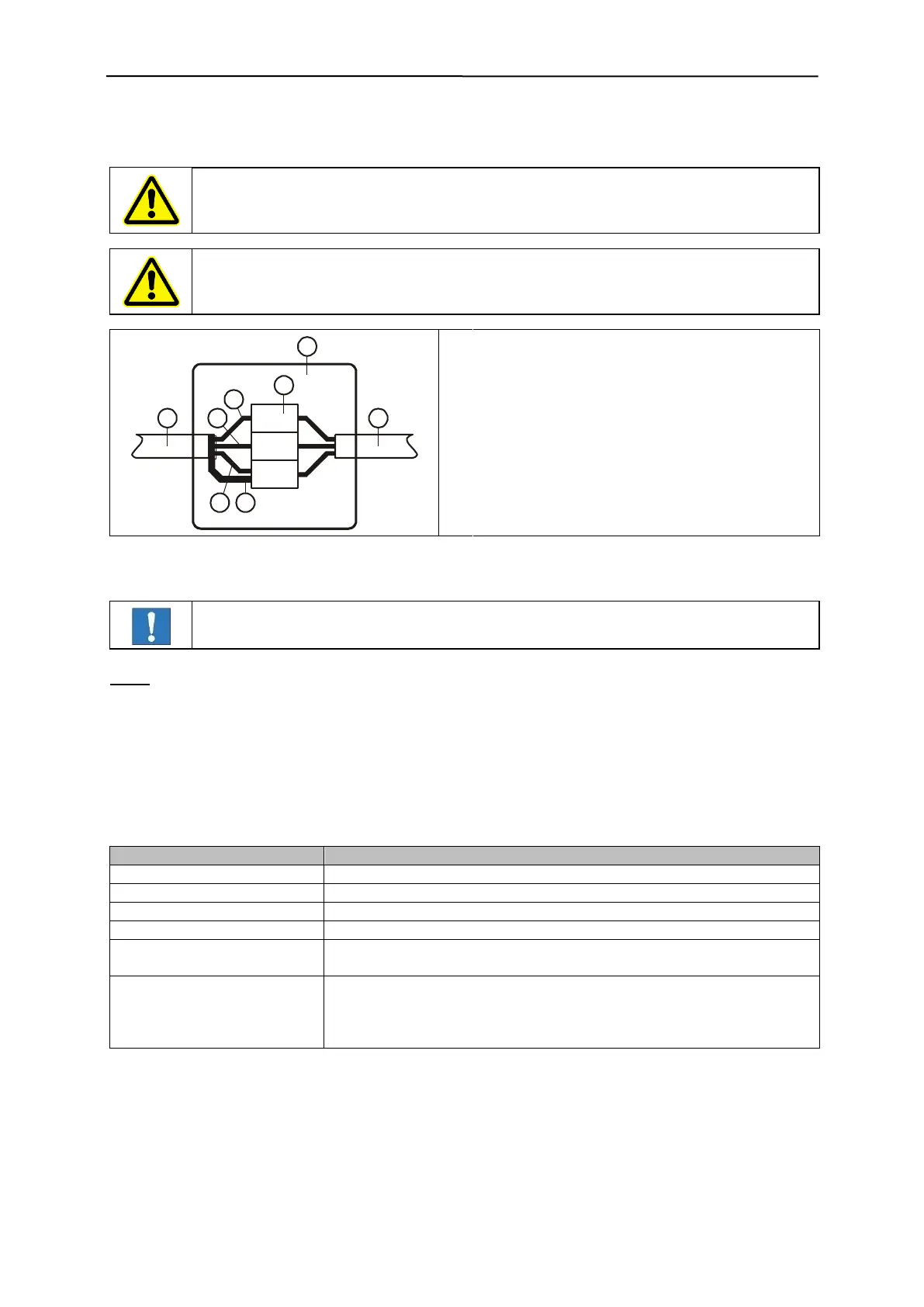
3. Feed cable into connection box according to diagram below.
Make sure that the mains supply is switched off.
Use a suitable shutdown unit i.e. emergency switch.
Conductor 1 (black) To terminal L
Conductor 2 (black) To terminal N
Conductor PE (yellow/green) To terminal PE
4. Close the terminal box
5. The unit is ready for operation approximately 5 seconds after switching it on.
IMPORTANT! Connect the shield to PE
Note:
The mains cable has a wire cross-section of 1.5 mm². The mains supply fuse protection should be set
accordingly.
The electronic board contains no alternating mains fuse.
5.2.7 Behaviour of machine at start up
Lamps and outputs during start-up phase:
Contact status with parameter "Metal at power on = [ ]"
Contacts 71 and 72 closed (equal to no metal alarm)
Contacts 81 and 82 closed (consistent with fault status)
MV1 / MV2 / MV3 switching
outputs
High active or Low active, depending on system setup
LM = Lamp metal "on"
LB = Lamp operation "on"
LF = Lamp fault "on"
Mz = Metal counter "inactive"
LM, LB and LF „on“ Function test lamp in the start-up phase.