2. Design and method of operation
12
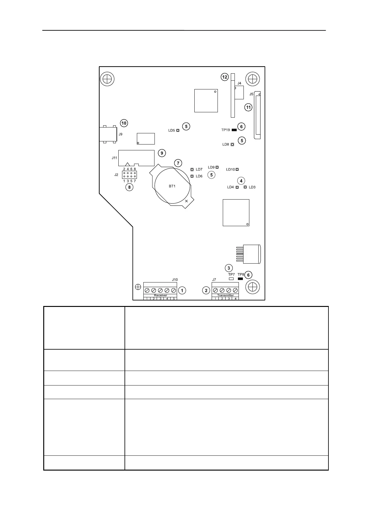
2.2.4 PRIMUS+ / CU electronics board
Connectors and terminals:
(1) "Receiver" J10, input signal from the detection coil
(2) "Transmitter" J7, output signal to the detection coil
(9) "Service interface" J11, diagnostics interface
(11) "FFC connector" J5, ribbon cable connector to the display module
(12) "Memory" J4, system / product data
(3) "Transmitter signal" TP7, sine signal ( 25Vss) to the detection coil
(6) "GND" TP8, TP19, reference ground for all signals
(8) "Service jumper" J2, 5-6, plugged, enable, program update
Interface/plug connectors:
(10) "Program update" J9, mini USB, (only for trained staff)
(JP2, observe jumper position)
(5) "Monitor LED,s, Vcc" LD 5, +24V
LD 6, +5V
LD 7, -5V
LD 8, +15V
LD 9, -15V
LD 10, 3.3V
(4) "Monitor LED’s" LD 4, green, operating status
LD 3, red, fault status
(12) "Memory devices" J4, device and product data
(7) "Battery" BT1, for real-time clock