AL-1551CS ELECTRICAL SECTION 12 - 12
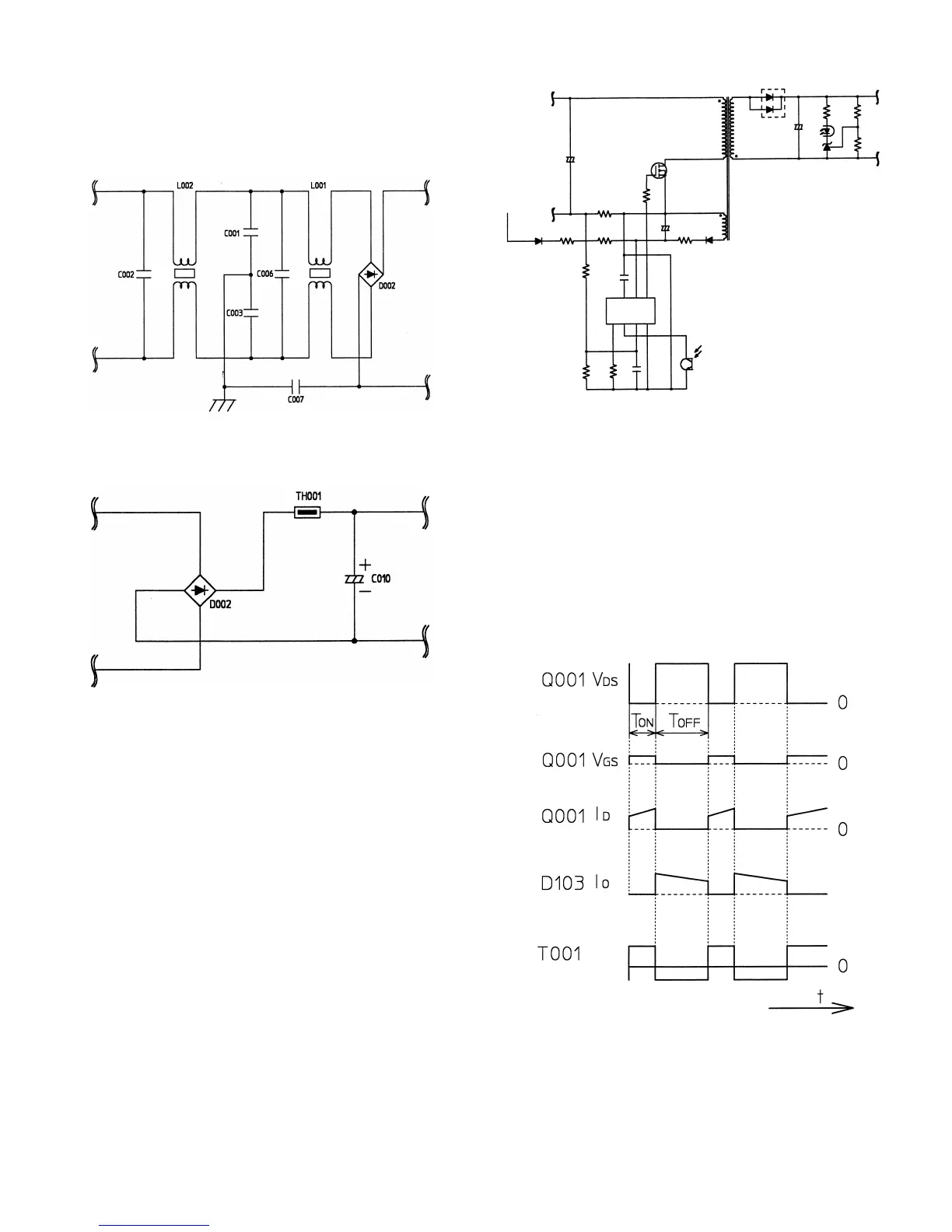
(1) Noise filter circuit
The filter circuit is composed of L and C. It reduces common noises
and normal mode noises generated from the AC line.
The common noise means that generated in each line for GND. Its
noise component is delivered through C001, C003, and C007 to GND.
The normal noise means that overlapped in the AC line or the output
line. It is attenuated by C002, L001, C006, and L002. Refer to fig (2).
fig (2) Noise filter circuit
(2) Rush current prevention circuit and rectifying/
smoothing circuit
fig (3) Rush current prevention, rectifying/smoothing circuit
Since the AC power is directly rectified, if there were not this rush cur-
rent prevention resistor (TH001), an extremely large rush current
would flow due to a charging current flowing through the smoothing
capacitor C010 when turning on the power.
To prevent against this, the rush current prevention resistor TH001 is
provided between the rectifying diode D002 and the smoothing diode
C010, suppressing a rush current.
The rectifying/smoothing circuit rectifies a 50/60Hz AC voltage with the
rectifying circuit, and smoothes it with the smoothing capacitor C010.
(3) Inverter and control circuit (Flyback converter system)
fig (4) Inverter and control circuit
This circuit is one-stone separate excitation DC-DC converter called
flyback converter, as shown in fig (4).
When an electromotive voltage of IC is applied through D012, R005,
and R006 to IC002, IC002 oscillates to conduct Q001.
As a result, a voltage is applied to the primary winding of the converter
transformer (T001) and at the same time a voltage is generated in the
driving winding of IC002 to operate IC002. Then IC002 turns ON/OFF
Q001 at the frequency of about 70KHz determined by R016.
Under the ON state, the voltage in the secondary winding is reversed
to the diode D103 and no current flows through the secondary winding
of T001.
Under the OFF state, the current flowing through the primary winding is
in the same direction as the primary winding, conducting D103 and
transmitting energy to the secondary winding. Refer to fig (4).
fig (5) Operation waveform of the flyback converter
T001
D103
R109R111
PC002IC102
Q001
R012
R006R005
R013
C013
R012
AC
876
IC002
R016
5
1234
PC002
C010
secondary
winding
voltage
 Loading...