AL-2041 DISASSEMBLY AND ASSEMBLY 8 - 15
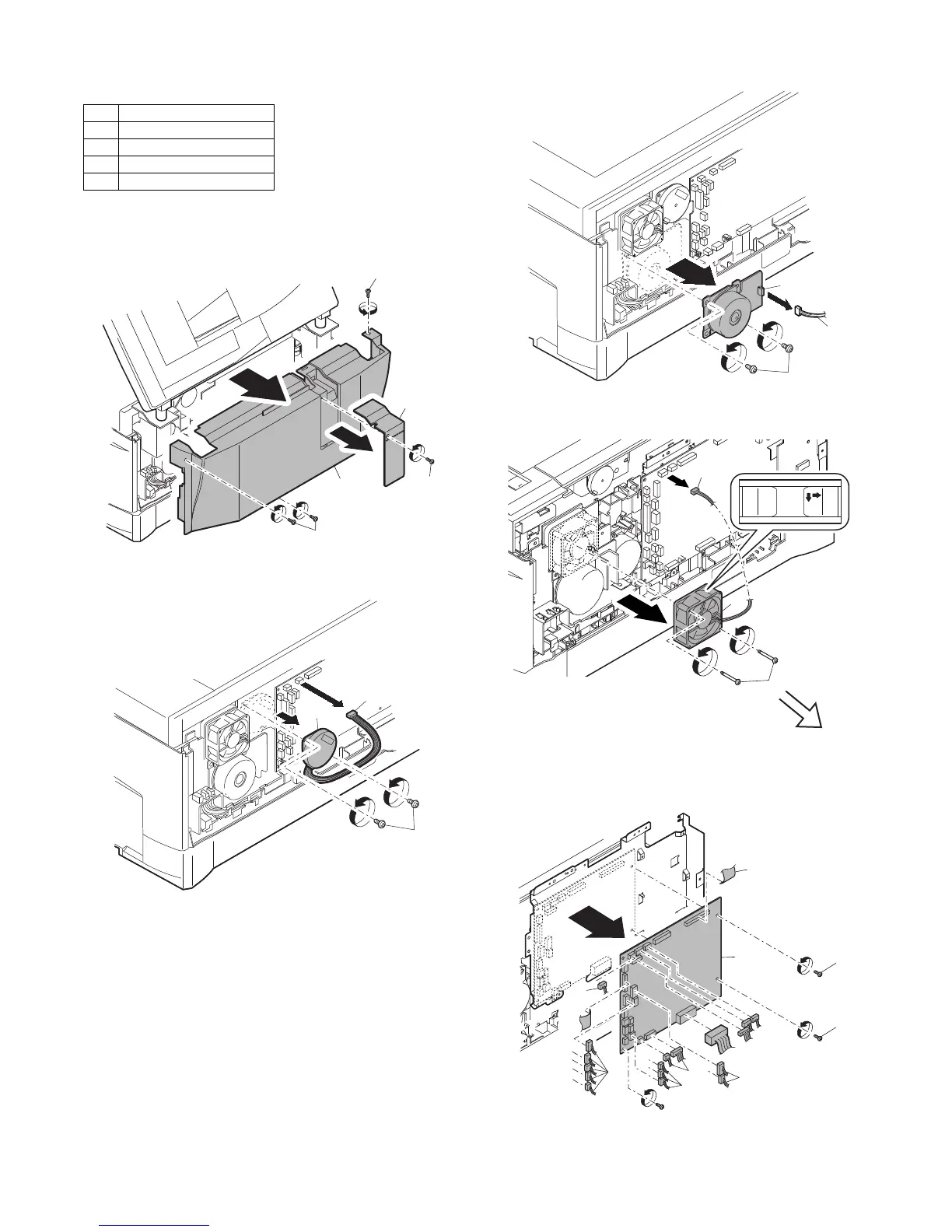
7. Rear frame section
A. List
B. Disassembly procedure
1) Remove four screws, and remove the rear cabinet and the rear
cabinet cover.
2) Disconnect the connector.
3) Remove two screws, and remove the scanner motor.
4) Remove two screws and one harness, and remove the main
motor.
5) Remove two screws and one connector, and remove the
exhaust fan motor.
6) Disconnect the connectors.
7) Remove the five screws, and remove the MCU PWB. (The
shape of the MCU PWB differs depending on the model.)
C. Assembly procedure
For assembly, reverse the disassembly procedure.
No. Part name Ref.
1 Scanner motor
2 Main motor
3 Exhaust fan motor
4 Main PWB
3)
1)
1)
1)
1)
1)
2)
2)
1)