AL-2041 ADJUSTMENTS 9 - 6
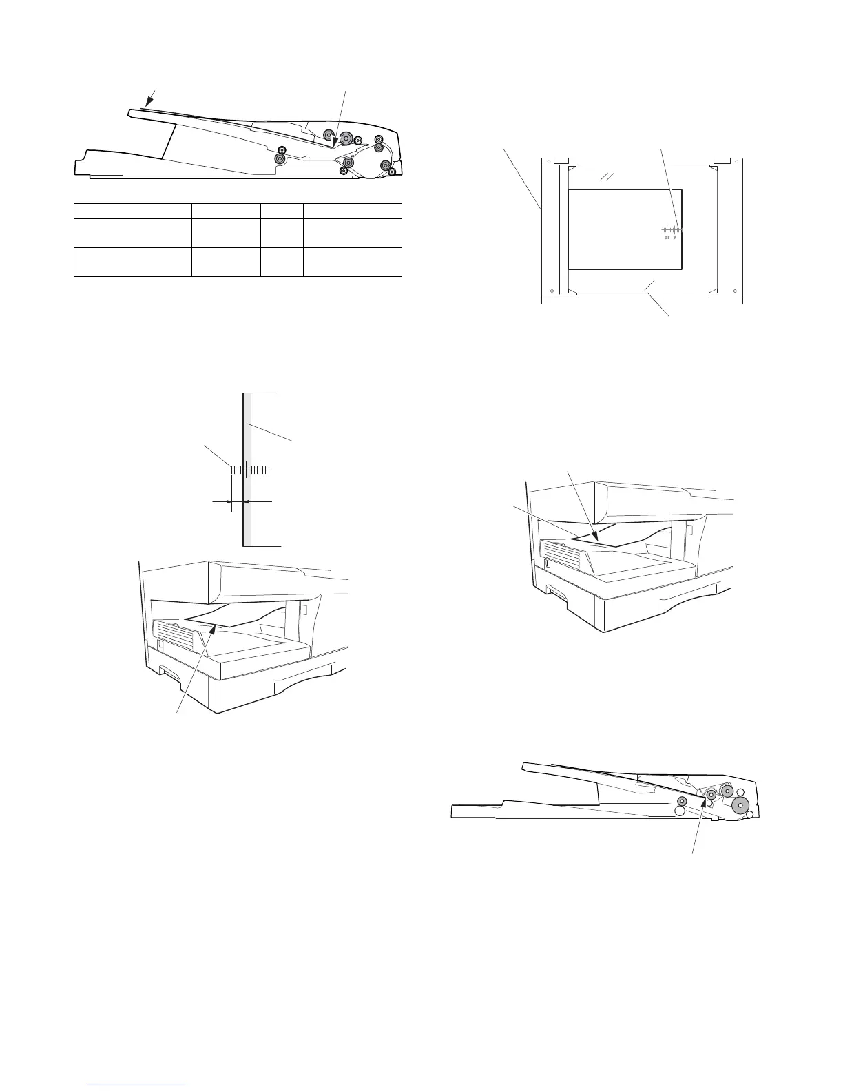
2) Set the test chart so that the scale is positioned as shown
below, in the S-D mode and the D-S mode.
3) Execute simulation 50-18.
Select the SPF memory reverse output position, and press
[START] key to make a copy.
Adjust the setting so that the front edge image loss is less than
4.0 mm in the SPF mode.
An increase of 1 in setting represents an increase of 0.1 mm in
image loss.
B. Adjusting trailing edge void in duplex copy
mode
This is the adjustment of the first surface printing mode (rear end
void) in duplex copying.
In a duplex copying operation, the paper is delivered starting from
the rear end of the first printing surface. It is therefore necessary to
make a void area at the rear end on the first printing surface to pre-
vent paper jam at the fusing part.
There are two adjustment modes:
1) Paper trailing edge void quantity 50-19 (TEXT)
This adjustment is made when the cassette paper size is rec-
ognized. The trailing edge void quantity can be adjusted by
changing the trailing edge image laser OFF timing.
2)
Print start position (Duplex back surface) (
SPF
) 50-19 (PHOTO)
The size (length) of a document read from the SPF is detected,
the image at the trailing edge of the first printing surface is cut
to make a void area. (The adjustment of void quantity at the
time when the cassette paper size is not recognized.)
The paper void quantity should be first adjusted before the image
cut trailing edge void quantity (SPF) is adjusted.
(Adjustment procedure)
(1) Paper trailing edge void quantity
1) Preparing test chart (Draw a scale at the rear end of one side of
a sheet of A/4 white paper or letter paper)
2) Set the test chart on the document glass as shown below.
3) Using the user simulation [18], set the paper size of the first
cassette.
• Letter paper: 4
• A4 paper: 3
4) Execute SIM 50-19 to turn on the TEXT lamp and make the
printing mode in OC-D mode.
Make a copy of the test chart to check the void area of the scale
on the image.
Adjust the setting so that the void area is 4 - 5 mm. An increase in
1 of setting represents 0.1 mm in void area.
(2) Print start position (Duplex back surface)
1) Set the test chart so that the scale is positioned as shown
below.
2) Execute SIM 50-19 to turn on the PHOTO lamp and make the
printing mode in the S-D mode.
3) Remove and reinsert the cassette.
Note: Make sure to carry out this step before making a copy
during this adjustment.
4) Make a copy and check the void area of the scale on the
image.
Adjust the setting so that the void area is 2 - 4 mm. An
increase of 1 in setting represents an increase of 0.1 mm in
void area.
Void position to be checked
Mode Display item Default LED
OC memory reverse
output position
OC 50 COPY mode lamp
SPF memory reverse
output position
SPF 50 PRINT mode lamp
Scale (S-D mode) Scale (D-S mode)
510
The front edge of the
scale on test chart
Front edge of paper
Void area
less than 4 mm
2nd printing surface where scale is printed (lower side)
Document guide
The trailing edge has a scale
Table glass
The trailing edge void on the first printing surface
is shown above.
Paper
Void position to be check