Do you have a question about the Sharp CD-DVD500 and is the answer not in the manual?
| Brand | Sharp |
|---|---|
| Model | CD-DVD500 |
| Category | Home Theater System |
| Language | English |
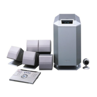
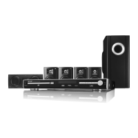
Power, dimensions, weight, and general system details.
Supported disc types, output formats, and tuner frequency ranges.
Output power, impedance, and speaker details for each component.
Frequency response, S/N ratio, and wow/flutter for the cassette deck.
Identifies buttons, switches, and indicators on the front panel.
Lists and explains the various display indicators on the front panel.
Details the various input/output terminals on the rear panel.
Identifies buttons and functions on the remote control transmitter.
Exploded views and part numbers for all speakers.
Step-by-step guide for setting the clock on the unit.
Guide for clearing settings and preparing the unit for transport.
Common issues and solutions for general system problems.
Specific troubleshooting for playback, tuner, and cassette deck.
Troubleshooting for remote control and condensation-related malfunctions.
Lists accessories and provides remote control battery installation instructions.
Guide for connecting external devices and speaker placement.
Steps for initial power-on, connecting to TV, and disc playback.
Instructions for playing discs, listening to radio, and playing cassettes.
Safety guidelines and initial steps for disassembling the main unit.
Detailed steps for disassembling the main unit, including screws and connectors.
Continues detailed steps for removing internal components like PWBs.
Steps for disassembling the front speaker components.
Procedures for removing and reinstalling tape heads, pinch rollers, and belts.
Adjustments for tape mechanism, torque, speed, and tuner sections.
Procedures for entering test modes and registering broadcast stations.
Visual references for adjustment points and automatic calibration.
Steps to enter and operate DVD test and ROM renewal modes.
Details on performing dynamic tests for DVD laser and motor functions.
Procedures for jump tests and spin offset adjustments.
Lists system errors, display messages, and handling precautions.
Block diagrams for RF, servo, motor drivers, and buffer amplifiers.
Block diagrams for DRAM, decoder, tuner, and audio processing.
Block diagrams for tape mechanism, Dolby, microcomputer, and power supply.
Block diagrams for amplifiers and speaker output connections.
Detailed circuit diagrams for the DVD Servo PWB.
Detailed circuit diagrams for the Main PWB.
Detailed circuit diagrams for the Display PWB.
Circuit diagrams for the Transformer and Power PWBs.
Circuit diagrams for the Amplifier and Dolby PWBs.
Circuit diagrams for motor and tape mechanism PWBs.
Wiring layout for the Main PWB.
Wiring layout for the Display PWB.
Wiring layout for the Power Supply PWBs.
Wiring layout for the Amplifier PWBs.
Wiring layout for the Dolby PWB.
Wiring layout for Motor and Tape Mechanism PWBs.
Explains conventions for resistors, capacitors, transistors, and LEDs.
Flowchart for diagnosing problems with disc rotation and pickup.
Flowchart for diagnosing 'No Disc' errors related to focus servo.
Flowcharts for diagnosing recognition, signal, and servo issues.
Flowchart for diagnosing picture/sound operation and RF signal problems.
Pin functions and block diagram for the Servo ECC IC.
Pin functions and block diagram for the RF Signal Processor IC.
Pin functions and block diagram for the Track Buffer Interface IC.
Pin functions and block diagram for the Motor Driver IC.
Pin functions and block diagram for the DVD Microcomputer IC.
Pin functions and diagrams for the Dolby Decoder IC.
Pin functions and diagrams for the 6-Ch Code IC.
Pin functions and diagrams for the Audio Processor IC.
Pin functions and diagrams for the Electronic Volume IC.
Pin functions and diagrams for the System Microcomputer IC.
Pin functions and diagrams for I/O Expander ICs.
Table mapping display segments to PWB pins for anode connections.
Information on ordering replacement parts, including contact details.
Explains conventions for resistors, capacitors, transistors, and LEDs.
List of resistors with part codes and values.
List of capacitors with part codes and values.
Continues list of capacitors with part codes and values.
Continues list of resistors with part codes and values.
Continues list of resistors with part codes and values.
Continues list of resistors with part codes and values.
Continues list of resistors with part codes and values.
Continues list of resistors with part codes and values.
Continues list of resistors with part codes and values.
Lists various connectors, switches, and other small parts.
Lists miscellaneous service parts like lenses, motors, and brackets.
Lists speaker box parts and packing materials.
Lists the various PWB assemblies for the system.
Continues listing speaker box parts and packing materials.
Exploded view diagram showing the assembly of the main unit cabinet.
Exploded view diagram showing the assembly of the DVD mechanism and chassis.
Exploded view of the front speaker components.
Exploded view of the center speaker components.
Exploded view of the surround speaker components.
Shows the default positions for switches and knobs during packing.
Instructions for packing the main unit and speakers.