EasyManua.ls Logo

Shield Shiel A-XT - User Manual

Shield Shiel A-XT
137 pages
Print Icon
To Next Page IconTo Next Page
Loading...
Shield Fire, Safety and Security Ltd.
Shield A-XT Releasing Fire Control Panel - Installation and Operation Manual SEXTCP-OM
Revision E01.00 Issue Date: 5/2/2012
Shiel A-XT
®
Releasing Fire Control Panel
Installation and Operation Manual

Table of Contents

Questions and Answers

  • A
    Alexa PearsonSep 9, 2025
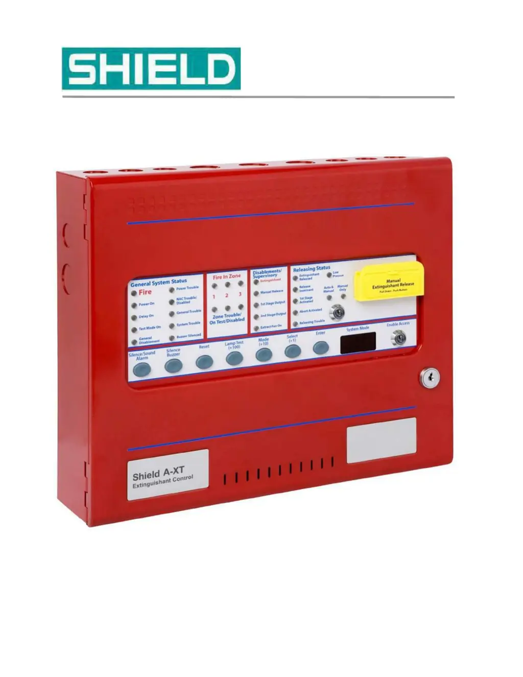
    What does Manual Release Trbl mean on Shield Shiel A-XT Control Panel?
    • E
      emilynormanSep 9, 2025
      If the Shield Control Panel displays 'Manual Release Trbl', it indicates a short or open circuit on the manual release switch input. Remove wiring and reconnect EOL. Check manual release circuit wiring.
  • S
    Stephen AdamsSep 12, 2025
    What does Mode Trbl mean on Shield Shiel A-XT?
    • J
      John CollinsSep 12, 2025
      If the Shield Control Panel displays 'Mode Trbl', it indicates a short or open circuit exists on the mode switch input. Remove wiring and reconnect the EOL. Check mode circuit wiring.
  • T
    terri97Sep 13, 2025
    What does Release Trbl mean on Shield Shiel A-XT Control Panel?
    • D
      Diana HickmanSep 13, 2025
      If the Shield Control Panel displays 'Release Trbl', it indicates a short or open circuit exists on the released pressure switch input. Remove wiring and reconnect end of line. Check released pressure switch circuit wiring.
  • M
    Marcus ThomasSep 15, 2025
    What does Low Pres Trbl mean on Shield Shiel A-XT?
    • F
      frederick12Sep 15, 2025
      If the Shield Control Panel displays 'Low Pres Trbl', it indicates a short or open circuit exists on the low pressure switch input. Remove wiring and re-connect the EOL. Check low pressure switch circuit wiring.
  • L
    Lindsey TaylorSep 17, 2025
    What does Tell Tale mean on Shield Shiel A-XT and how to reset it?
    • C
      Carlos WilliamsSep 18, 2025
      If the Shield Control Panel displays 'Tell Tale', it means the panel mounted or remote manual release button has been pressed. It can only be reset by pressing processor reset and W/DOG reset or powering down the fire control panel.

Summary

Section 1 Introduction

Using This Manual

Guide to effectively navigate and utilize the manual's content for installation and operation.

Document Conventions and Help

Explains document conventions, how to get technical help, and repair/return policies.

Returns and Repairs Policy

Details policies for in-warranty, out-of-warranty, damaged, and returned items.

Section 2 Overview

Hardware Features

Description of the physical components and hardware aspects of the Fire Control Panel.

Panel Controls and Indicators

Detailed explanation of the front-panel controls and indicator LEDs for system operation.

Field Terminals Overview

Explanation of the terminal layout and function for field wiring connections.

Section 3 Installation

Installation Checklist and Preparation

Covers the initial checklist, site selection, and preparation steps for installation.

Mounting the Fire Control Panel

Detailed instructions for panel mounting, including fascia removal and anchoring.

AC Power and Battery Cabling

Guidance on connecting AC power and standby batteries to the panel.

Field Cabling and Detection Zones

Instructions for field wiring, including detection zones and supervised inputs.

Notification Appliance and Releasing Circuits

Details connections for NACs, NAC extenders, and releasing device circuits.

Auxiliary Outputs and Relays

Explanation of AUX 24V, status unit terminals, and relay outputs.

Installation Testing and Troubleshooting

Procedures for testing the installed system and troubleshooting common issues.

Section 4 Programming and Operating

Programming the Fire Control Panel

Steps to access Access Level 3 and configure the panel using system mode codes.

Configuration Codes Explained

Comprehensive list and description of available configuration codes for panel programming.

Panel Operation and Access Levels

How to operate the panel using access levels and controls.

System Functions and Conditions

Explains how the panel handles fire conditions, alarms, and various operational functions.

Test Mode and Disablements

Procedures for entering test mode and disabling specific panel functions or zones.

Section 5 Maintenance and Repair

Cleaning, Testing, and Battery Inspection

Procedures for cleaning, testing the releasing system, and inspecting batteries.

Battery and Fuse Replacement

Instructions for replacing standby batteries and fuses in the control panel.

Section 6 Supplementary Devices

Status Unit Functionality and Connections

Details the purpose, connections, and jumper settings for Status Units.

Ancillary Board Features and Relays

Describes Ancillary Boards, their connections, relay contacts, and power.

Device Configuration and Management

Instructions for configuring, adding, and removing Status Units and Ancillary Boards.

Abort and Mode Select Functions

Explanation of abort connections and mode select key switch functionality.

Appendix A Specifications

Power Supply and Battery Specs

Details electrical specifications for power supply, battery circuit, and limitations.

Circuit and Terminal Specifications

Covers specs for ground fault, wiring, IDC, NAC, Releasing, Relays, Aux 24V, Status, Ancillary.

Operating Environment and Physical Specs

Specifies operating temperature, humidity, and physical dimensions of the panel.

Appendix B Calculations

Amp-Hour Rating and Current Loading

Explains how to calculate amp-hour rating and current loading for battery sizing.

Wiring Length Calculations

Provides methods for calculating maximum wire length for NAC and Releasing circuits.

Appendix C Wiring Diagram

Wiring Diagram Overview

Introduces the wiring diagrams provided for the Shield A-XT Releasing Fire Control Panel.

Appendix D Operating Instructions

Basic Panel Operations

Step-by-step instructions for common panel operations and functions.

Battery Inspection and Documentation

Instructions for inspecting batteries and references for related documents.

Appendix E UL Compliance Label

UL Compliance Information

Details UL compliance information, model numbers, and system features.

Appendix F UL 864 Permitted Configurations

Permitted Configuration Options

Lists programming features and options permitted under UL 864 standards.

Shield Shiel A-XT Specifications

General IconGeneral
BrandShield
ModelShiel A-XT
CategoryControl Panel
LanguageEnglish