- 2 -
Contents
1. Safety Rules ................................................................. 3
2. Introduction ................................................................... 4
2-1. Check before Use .................................................. 4
2-2. Handling Instruction ............................................... 4
3. Installation and Wiring .................................................. 4
3-1. Installation Site (environmental conditions) ............ 4
3-2. Mounting ................................................................ 5
3-3. External Dimensions and Panel Cutout .................. 5
3-4. Wiring ..................................................................... 5
3-5. Terminal Layout ...................................................... 6
3-6. Terminal Arrangement Table ................................... 6
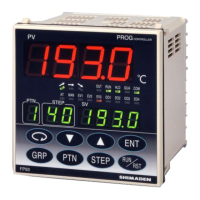
4. Names and Functions of Parts on Front Panel ............. 7
5. Explanation of Screens and Setting ............................. 9
5-1. Parameter Flow ...................................................... 9
(1) How to Move from Screen Group to Screen Group and
Explanation of Screen Groups ......................................... 9
5-2. Application of Power and Display of Initial Screen 13
5-3. How to Change Screens ...................................... 13
(1) How to Change Screen Groups 0 - 5 ............................. 13
(2) How to Change Screen in Screen Group 0 .................... 13
(3) How to Change Screen in Screen Group 3 .................... 14
(4) How to Change Set Values (Data) ................................. 14
5-4. Before Starting Up ................................................ 14
(1) Checking Wiring ............................................................. 14
(2) Applying power ............................................................... 14
(3) Setting Measuring Range .............................................. 14
(4) Setting Control Mode ..................................................... 14
(5) Setting Control Output Characteristic ............................ 14
(6) Setting Other Data ......................................................... 14
(7) Note on Initialization upon Change of Data ................... 14
5-5. Explanation of Screen Group 0 and Setting ......... 15
(1) Setting HLD Execution ................................................... 15
(2) Setting ADV Execution ................................................... 15
(3) Setting Auto Tuning (AT) Execution ............................... 15
5-6. Explanation of Screen Group 1 and Setting ......... 15
(1) Setting Start SV ............................................................. 15
(2) Setting End Step ............................................................ 15
(3) Setting Time Signal ........................................................ 16
(4) Setting Event Action Point .............................................. 16
(5) Setting the Number of Program Executions ................... 16
(6) Setting PV Start ............................................................. 16
(7) Setting Guarantee Soak Zone ....................................... 17
5-7. Explanation of Screen Group 2 and Setting ......... 17
(1) Setting Step SV .............................................................. 17
(2) Setting Step Time ........................................................... 17
(3) Setting PID No. .............................................................. 17
5-8. Explanation of screen Group 3 and Setting .......... 17
(1) Setting ON/OFF of FIX Mode ......................................... 17
(2) Setting FIX SV Value...................................................... 17
(3) Setting FIX No. ............................................................... 17
(4) Setting FIX Event Action Point ........................................ 17
5-9. Explanation of screen Group 4 and Setting .......... 18
(1) Setting Outputs of PID Nos. 1 – 6 ................................... 18
(2) Setting Zone PID ............................................................ 18
5-10. Explanation of Screen Group 5 and Setting........ 18
(1) Setting the Number of Patterns ...................................... 18
(2) Setting Time Unit ............................................................ 19
(3) Setting With/Without Power Failure Compensation ........ 19
(4) Setting Input Abnormality Mode ...................................... 19
(5) Setting Measuring Range Code ...................................... 19
(6) Setting Input Unit ............................................................ 19
(7) Setting Input Scaling ....................................................... 19
(8) Setting PV Bias ............................................................... 19
(9) Setting PV Filter .............................................................. 19
(10) Setting Output Control Characteristic ........................... 19
(11) Setting Proportional Cycle............................................. 19
(12) Setting SV Limiter ......................................................... 19
(13) Setting External Control Input ....................................... 20
(14) Setting Events ............................................................... 20
(15) Setting Status Output (DO) ........................................... 21
(17) Setting Communication ................................................. 21
(18) Setting Keylock ............................................................. 22
5-11. Measuring Range Codes Table ........................... 22
6 Operation and Functions .............................................. 23
6-1. Using FIX Mode .................................................... 23
6-2. Setting Target Value (SV) (FIX Mode) ................... 23
6-3. Setting Output Manually ....................................... 23
6.4. Auto Tuning (AT) ................................................... 23
6-5. PID Action............................................................. 24
6-6. Manual Reset ....................................................... 24
6-7. Output Lower Limit and Higher Limit Setting Limiters
............................................................................. 24
6-8. Proportional Cycle Time........................................ 24
6-9. Zone PID .............................................................. 25
6-10. External Control Input (DI) .................................. 25
6-11. Events ................................................................. 26
6-12. Setting Event Standby Action ............................. 26
6-13. Diagrams of Alarm Actions Selectable as Event . 26
6-14. Event and Status Output Actions ........................ 26
6-15. Time Signal ......................................................... 27
6-16. Status (DO) Output ............................................. 28
6-17. Auto Return Function .......................................... 28
6-18. Notes on RAM as Communication Memory Mode28
7. Error Codes, Causes and Remedies .......................... 28
8. Record of Parameter Setting ...................................... 29
9. Specifications .............................................................. 33