- 33 -
9. Specifications
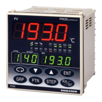
Ŷ Display
Ɣ Display means Digital display : PV Red 7 segments LED 4 digits
: SV Green 7 segments LED 4 digits
: PTN Green 7 segments LED 1 digit
: STEP Green 7 segments LED 2 digits
Status display : OUT Green LED lamp indication
: EV1 - 3 (3 points) Orange LED lamp indication
: AT Green LED lamp indication
: MAN Green LED lamp indication
: COM Green LED lamp indication
: DO1 - 4 (4 points) Green LED lamp indication
: GUA Green LED lamp indication
: RUN Green LED lamp indication (blinks during FIX)
: HLD Green LED lamp indication
: "ascend" Green LED lamp indication
: "level" Green LED lamp indication
: "descend" Green LED lamp indication
Ɣ Display accuracy : ± (0.3%FS + 1 digit), with restriction depending on measuring range, CJ error excluded.
Ɣ Display accuracy maintaining range : 23˚C±5˚C
Ɣ Display resolution : Differs by measuring range (0.001, 0.01, 0.1 and 1)
Ɣ Measured value display range : –10% - 110% of measuring range (–210 - 680˚C for Pt –200 - 600˚C range)
Ɣ Display updating cycle : 0.25 second
Ɣ Input scaling : Possible during linear input (current and voltage)
(–1999 - 9999, span 10 - 5000, decimal point position variable)
Ŷ Setting
Ɣ Local Setting : Operated by 8 keys ( , , , , , ) on the front panel
Ɣ SV setting range : Same as measuring range (within setting limiter)
Ɣ Setting limiter : Individual setting for higher and lower limits, any value is selectable within measuring range
(Lower limit < Higher limit)
Ɣ Keylock : OFF, 1 - 3 (4 levels)
Ɣ Setting of unit : ˚C or ˚F selectable for sensor input
Ŷ Input
Ɣ Type of input : Selectable from multiple (TC, Pt, mV, V) and current (mA)
Ɣ Thermocouple : Input impedance 500 k minimum
: External resistance tolerance 100 maximum
: Influence of lead wire tolerance 1.2μ V/10
: Burnout function standard up scale
: Cold junction compensation accuracy Within the accuracy maintaining range ±1 ˚C Ambient
temperature 5 – 45 ˚C ±2 ˚C
*1: For K, T and U thermocouples with indication values below –100 ˚C, ±0.7% FS
*2: Accuracy guarantee not applicable to B thermocouple below 400 ˚C (752 ˚F).
Ɣ R.T.D. : Normal current: 0.25 mA
: Lead wire tolerance 5 maximum/wire (3 lead wires should have the same resistance.) Influence
of lead wire tolerance (error in temperature)
0.3˚C maximum in the case of 5
/wire
0.7˚C maximum in the case of 10 /wire
1.6˚C maximum in the case of 20 /wire
Ɣ Voltage : Input impedance 500 k minimum
Ɣ Current : mA to be taken care of by external resistor 250
Ɣ Sampling cycle : 0.25 second
Ɣ PV filter : 0 - 100 seconds
Ɣ PV bias : –1999 - 2000 digits
Ɣ Isolation : Not insulated from system and DI but insulated from others
Ŷ Control
Ɣ Control mode : Expert PID control with auto tuning function
RA (heating)/DA (cooling) action
Ɣ Type of control output/rating : Contact 1c 240V AC 2.5A (resistive load) 1.0A (inductive load)
SSR drive voltage12V±1.5V DC (Maximum load current 30mA)
Current 4 - 20mA (Maximum load resistance 600 )
Current 4 - 20mA (Maximum load resistance 600 )
Voltage 0 - 10V (Maximum load current 2mA)
Ɣ Resolution : About 1/8000
Ɣ Accuracy of output : ±1.0% FS (5 - 100%)
Ɣ Control output
Proportional band (P) : OFF or 0.1 - 999.9% FS (ON-OFF action by OFF)
Integral time (I) : OFF or 1 - 6000 seconds (P or PD action by OFF)
Derivative time (D) : OFF or 1 - 3600 seconds (P or PI action by OFF)
Target value function : OFF or 0.01 - 1.00
ON/OFF hysteresis : 1 - 999 digits
Manual reset : ±50.0% (Effective when I = OFF)

 Loading...