- 6 -
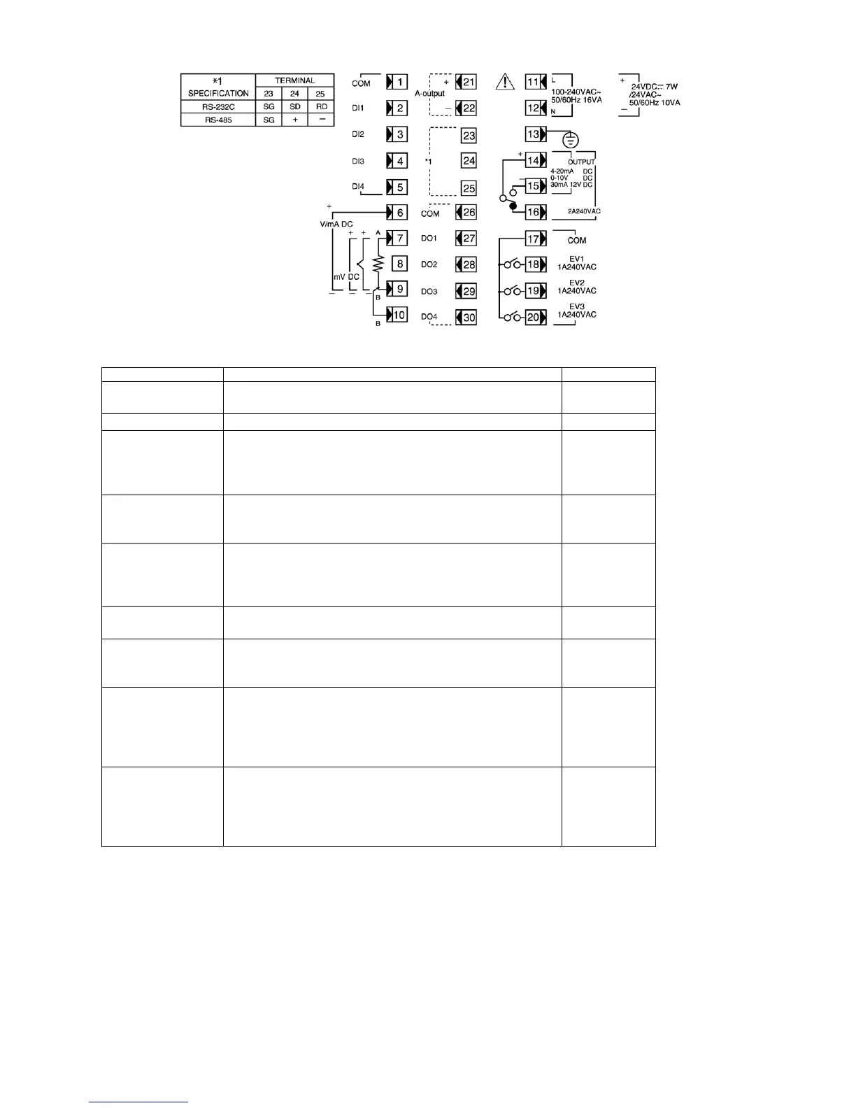
3-5. Terminal Layout
(Follow the terminal layout and terminal arrangement table shown below in your wiring operation.)
3-6. Terminal Arrangement Table
Name of terminal Description / Code Terminal No.
Power supply 100 - 240V AC/24V AC: L, 24V DC: +
100 - 240V AC/24V AC: N, 24V DC:
-
11
12
Protective conductor Protective grounding
Ã
13
Input Voltage (V) Current (mA): + 6
7
9
10
R.T.D.: A, thermocouple/Voltage (mV): +
R.T.D.: B, thermocouple/Voltage (mV, V), Current (mA): –
R.T.D.: B
Control output Contact: COM, SSR drive voltage/Voltage/Current: +
Contact: NO, SSR drive voltage/Voltage/Current: –
Contact: NC
14
15
16
Event output COM
EV1
EV2
EV3
17
18
19
20
Analog output
(option)
+
-
21
22
Communication
(option)
SG
RS-232C: SD, RS-485: +
RS-232C: RD, RS-485: –
23
24
25
External control input COM
DI1
DI2
DI3
DI4
1
2
3
4
5
Status output (DO)
(option)
COM
DO1
DO2
DO3
DO4
26
27
28
29
30
NOTE 1: With thermocouple, voltage, or current input, shorting across B and B terminal will cause an error. Leave terminal No.10 open.
NOTE 2: With voltage (V) or current (mA) input, don't connect anything with terminal No.7. Any connection with it may cause problems
with the instrument.