- 22 -
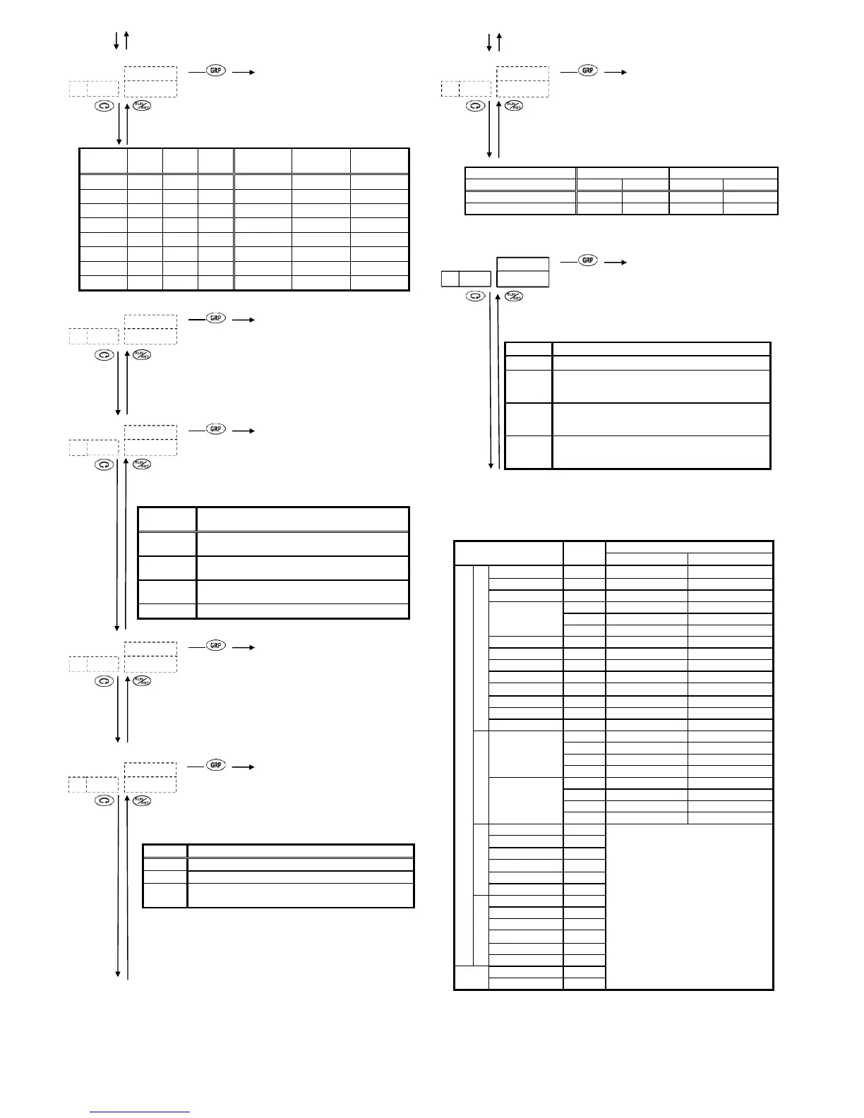
5-39 Communication data format setting screen
To 5-0 screen
Initial value: 7E1
Setting range: 8 types in the following table
A communication data format is set.
Selection
Data
length
Parity
Stop
bits
Shimaden
standard
MODBUS/
ASCII mode
MODBUS/
RTU mode
o~i
7 bits EVEN 1bit
żż
ʊ
o~j
7 bits EVEN 2bit
żż
ʊ
oi
7 bits None 1bit
ż
ż
ʊ
oj
7 bits None 2bit
ż
ż
ʊ
p~i
8 bits EVEN 1bit
ż
ʊż
p~j
8 bits EVEN 2bit
ż
ʊż
pi
8 bits None 1bit
ż
ʊż
pj
8 bits None 2bit
ż
ʊż
5-40 Start character setting screen
To 5-0 screen
Initial value:
Setting range: (STX) ࠊ (| @)
Which of STX and @ is used as the start character of
communication format is set.
5-41 BCC operation type setting screen
To 5-0 screen
Initial value: 1
Setting range: 1 ~ 4
An operation type for error detection BBC check is selected from
the following table:
Type of
Operation
Description
i
Add operation from start character to text end
character
j
2’s complement after add operation from start
character to text end character
k
Exclusive OR operation from 2nd character to
text end character
l
Without BCC operation
5-42 Communication delay time setting screen
To 5-0 screen
Initial value: 20
Setting range: 1 ~ 100
Minimum delay time lag from receiving a communication
command to transmission is set.
Minimum delay time = Set value × 0.512msec
5-43 Communication memory mode setting screen
To 5-0 screen
Initial value: ~~
Setting range: ~~, |, ¦~
Which of EEPROM and RAM data is written in through
communication is set.
Type Writing Process
~~ All to be written in EEPROM
|
All to be written in RAM
¦~
FIX SV, OUT and STEP SV to be written in RAM
and others in EEPROM
* Note on the RAM mode selected as communication mode: Since
all are written in RAM, setting inconsistency may arise in some case.
For details, refer to "6-17. Notes on RAM as Communication
Memory Mode."
To 5-44 screen
5-44 Communication mode type setting screen
To 5-0 screen
Initial value: COM1
Setting range: COM1, COM2
Selects type of communication mode.
Set to COM1 if you want to enable key operation while writing
by communication.
Communication mode t
COM1 COM2
Communication mod
Communication writing Availabl
(18) Setting Keylock
5-45 Keylock setting screen
To 5-0 screen
Initial value: OFF
Setting range: OFF, 1, 2, 3
Items which should not be changed are locked. Data are unable
to be changed on locked screens. Select OFF to release the lock.
Lock No. Range to be locked
Release of lock (All data allowed to be changed.)
i
Keylock of the screen groups 3, 4 and 5 (excluding
communication mode and special keys on
communication s
j
Keylock of screen groups 1, 2, 3, 4 and 5 (excluding
communication mode and special keys on
communication s
k
Keylock of all screens excluding RUN/RST on the
basic screen, communication mode screen and
s
To 5-0 Initial screen
5-11. Measuring Range Codes Table
Select a measuring range from the following table.
Note: A change of a measuring range code will initialize all data related
to the measuring range.
Input type Code
Measuring range
Υ ;
Multi-input
Thermocouple
B *1
hi
0 㹼1800 0㹼3300
R
hj
0 㹼1700 0㹼3100
S
hk
0 㹼1700 0㹼3100
K
*2
hl
-199.9㹼 400.0 -300㹼750
hm
0.0㹼 800.0 0㹼1500
hn
0 㹼1200 0㹼2200
E
ho
0 㹼 700 0㹼1300
J
hp
0 㹼 600 0㹼1100
T *2
hq
-199.9㹼 200.0 -300㹼400
N
ih
0 㹼1300 0㹼2300
PLϩ *3
ii
0 㹼1300 0㹼2300
WRe5-26 *4
ij
0 㹼2300 0㹼4200
U *5 *2
ik
-199.9㹼 200.0 -300㹼400
L *5
il
0 㹼 600 0㹼1100
R.T.D.
Pt
ki
-200 㹼 600 -300㹼1100
kj
-100.0㹼 100.0 -150.0㹼200.0
kk
-50.0㹼50.0 -50.0㹼120.0
kl
0.0㹼200.0 0.0㹼400.0
JPt
km
-200 㹼500 -300㹼1000
kn
-100.0㹼100.0 -150.0㹼200.0
ko
-50.0㹼50.0 -50.0㹼120.0
kp
0.0㹼200.0 0.0㹼400.0
mV
-10㹼 10mV
oi
Scaling possible.
Setting range: -1999 ~ 9999
Span: 10 ~ 5000
Decimal point position: 0.000 ~ None
0㹼 10mV
oj
0㹼 20mV
ok
0㹼 50mV
ol
10㹼 50mV
om
0㹼100mV
on
V
-1㹼 1
pn
mA
0㹼20mA
qi
4㹼20mA
qj
Thermocouple B, R, S, K, E, J, T, N: JIS/IEC
R.T.D Pt100: JIS/IEC; JPt100: Former JIS
*1 Thermocouple B: Accuracy guarantee not applicable to 400Υ(725
;
) and below.
*2 Thermocouple K, T, U: Accuracy of those whose readings are below -100Υ is ±0.7% FS.
*3 Thermocouple PLII: Platinel
*4 Thermocouple WRe 5-26: A product of Hoskins
*5 Thermocouple U, L: DIN 43710
When not designated, factory-set measuring range is K thermocouple (0.0 ~ 800.0Υ).
||
o~i
|
i
~
jh
}
i
~
~~
 Loading...