- 15 -
jwh
rh
i
c
d
e f
c
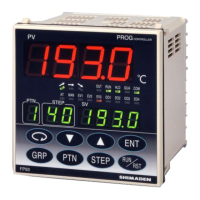
Measured value display (PV display)
d
Target set value display (SV display)
e
Pattern No. display (PTN display)
f
Step No. display (STP display)
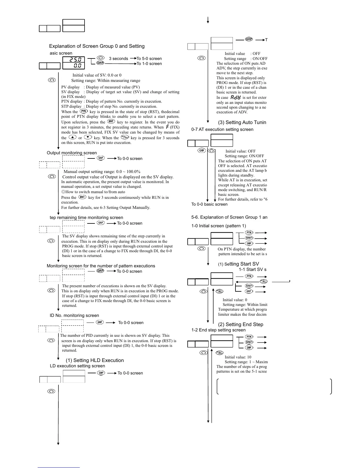
5-5. Explanation of Screen Group 0 and Setting
0-0 Basic screen
3 secondsTo 5-0 screen
To 1-0 screen
Initial value of SV: 0.0 or 0
Setting range: Within measuring range
PV display : Display of measured value (PV)
SV display : Display of target set value (SV) and change of setting
(in FIX mode)
PTN display : Display of pattern No. currently in execution.
STP display : Display of step No. currently in execution.
When the key is pressed in the state of stop (RST), thedecimal
point of PTN display blinks to enable you to select a start pattern.
Upon selection, press the key to register. In the event you do
not register in 3 minutes, the preceding state returns. When
(FIX)
mode has been selected, FIX SV value can be changed by means of
the or key. When the key is pressed for 3 seconds
on this screen, RUN is put into execution.
0-1 Output monitoring screen
To 0-0 screen
Manual output setting range: 0.0 ~ 100.0%
Control output value of Output is displayed on the SV display.
In automatic operation, the present output value is monitored. In
manual operation, a set output value is changed.
۔How to switch manual to/from auto
Press the key for 3 seconds continuously while RUN is in
execution.
For further details, see 6-3 Setting Output Manually.
0-2 Step remaining time monitoring screen
To 0-0 screen
The SV display shows remaining time of the step currently in
execution. This is on display only during RUN execution in the
PROG mode. If stop (RST) is input through external control input
(DI) 1 or in the case of a change to FIX mode through DI, the 0-0
basic screen is returned.
0-3 Monitoring screen for the number of pattern executions
To 0-0 screen
The present number of executions is shown on the SV display.
This is on display only when RUN is in execution in the PROG mode.
If stop (RST) is input through external control input (DI) 1 or in the
case of a change to FIX mode through DI, the 0-0 basic screen is
returned.
0-4 PID No. monitoring screen
To 0-0 screen
The number of PID currently in use is shown on SV display. This
screen is on display only when RUN is in execution. If stop (RST) is
input through external control input (DI) 1, the 0-0 basic screen is
returned.
(1) Setting HLD Execution
0-5 HLD execution setting screen
To 0-0 screen
Initial value: OFF
Setting range: ON/OFF
HLD is put in execution when ON is selected and selection of OFF
releases it. Upon execution of HLD, PROG execution is stopped
temporarily. The HLD lamp lights during the execution of HLD. This
screen is on display only when RUN is in execution in the PROG
mode. If stop (RST) is input through external control input (DI) 1 or
in the case of a change to FIX mode through DI, the 0-0 basic screen
is returned.
In case
is set for external control input (DI), it functions only
as an input status monitoring screen. ADV input is not valid during
the execution of HLD.
To 0-6 screen
(2) Setting ADV Execution
0-6 ADV execution setting screen
To 1-0 screen
Initial value : OFF
Setting range : ON/OFF
The selection of ON puts ADV in execution. Upon execution of
ADV, the step currently in execution is terminated and forced to
move to the next step.
This screen is displayed only when RUN is in execution in the
PROG mode. If stop (RST) is input through external control input
(DI) 1 or in the case of a change to FIX mode through DI, the 0-0
basic screen is returned.
In case
|
is set for external control input (DI), it functions
only as an input status monitoring screen. ADV is not valid for 1
second upon changing to a new step and for 2 seconds upon
execution of ADV.
(3) Setting Auto Tuning (AT) Execution
0-7 AT execution setting screen
Initial value: OFF
Setting range: ON/OFF
The selection of ON puts AT in execution and AT is released when
OFF is selected. AT execution is possible only when RUN is in
execution and the AT lamp blinks during AT execution. The lamp
lights during standby.
While AT is in execution, setting and changing are not possible
except releasing AT execution, keylock setting, communication
mode switching, and RUN/RST, HLD and ADV setting on the
basic screen.
For further details, refer to "6-4. Auto Tuning (AT)."
To 0-0 basic screen
5-6. Explanation of Screen Group 1 and Setting
1-0 Initial screen (pattern 1)
To 1-0 (pattern 2) screen
To 2-1 (step 1) screen
To 3-0 screen
On PTN display, the number (1 ~ 4; decimal point blinking) of a
pattern intended to be set is shown.
(1) Setting Start SV
1-1 Start SV setting screen
1-1 (pattern 2) screen
To 2-1 (step 1) screen
To 1-0 (pattern 1) screen
Initial value: 0
Setting range: Within limiter
Temperature at which program is started is set. A change in SV
limiter makes the four decimal place blinking.
(2) Setting End Step
1-2 End step setting screen
To 1-1 (pattern 2) screen
To 2-1 (step 1) screen
To 1-0 (pattern 1) screen
 Loading...

