VM-741 LOCAL COMMUNICATION &
PHASE MARKER MODULE
Page 3 of 4
VM-7 SERIES
SPECIFICATIONS
30909E1.2
Issued Feb. 2009
Revised Mar. 2010
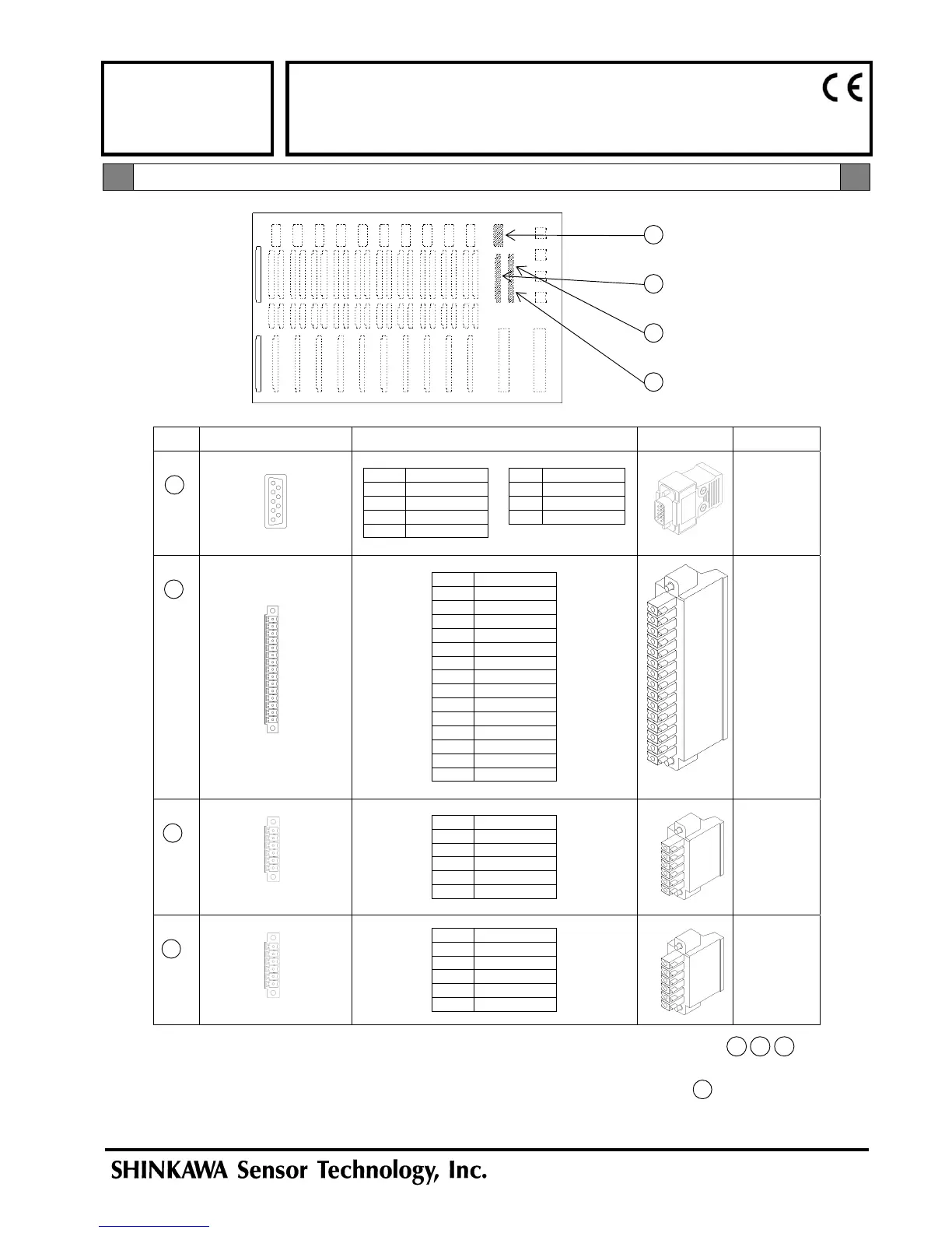
Back of Instrument Rack Plug/ Terminal Block (Connector) Pin Assignment Fitting Plug Part Code
1 CH1 MON 6 CH1 PUL
2 CH1 COM 7 CH1 COM
3 CH2 MON 8 CH2 PUL
4 CH2 COM 9 CH2 COM
5 N/A
Plug
7072NAD
Hood
7072NAG
A1 CH1 SIG
A2 CH1 COM
A3 N/A
A4 CH1 POW
A5 CH1 SHIELD
A6 CH2 SIG
A7 CH2 COM
A8 N/A
A9 CH2 POW
A10 CH2 SHIELD
A11 CH3 SIG
A12 CH3 COM
A13 N/A
A14 CH3 POW
A15 CH3 SHIELD
7072NAB
A1 RES
A2 RES
A3 SEQ
A4 SEQ
A5 FILT
A6 FILT
7072NAC
A1 N/A
A2 N/A
A3 N/A
A4 N.O.
A5 SYSTEM-OK
A6 N.C.
7072NAC
4
3
2
1
Plug/ Terminal Block (Connector) Pin Assignment
Note1) For the accessory specification code “/TB1”, the fitting terminal block plugs 2 3 4
are included.
For the accessory specification code “/TB1”, the D-sub plug and hood 1 are not included.
If required, please make necessary arrangement separately referring to the part code above.
1 Monitor Output Connector
2 Transducer Input Terminal Block
3 Top Contact Signal Input Terminal Block
4 Bottom Contact Signal Input Terminal Block
VM-761 Instrument Rack
(Back)
 Loading...