Non-incendive *
1
Custom set up Tropical spec.
1
Class I Division 2 CSA
*1 Pending
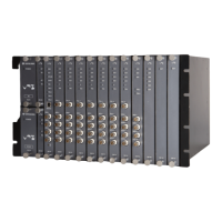
VM-732 ANALYSIS MODULE
Page 1 of 2
VM-7 SERIES
SPECIFICATIONS
ASYNCHRONOUSE WAVE DATA OUTPUT
No. of data points : 2048
Max. Sampling frequency : 25.6kHz
Collection interval : 10s (Min.)
TREND DATA OUTPUT
Items : Rotating Speed
Amplitude (Over-all, 0.5X, 1X, 2X, Not 1X)
Phase (0.5X, 1X, 2X)
GAP
Collection interval : 1s (Min.)
PROCESS DATA OUTPUT
Item : Displacement, Temperature
Collection interval : 10s (Min.)
COMMUNICATION to ANALYSIS VIEW(VM-773)
Ethernet specification : 100BASE-T
Max. distance Hub to nodes between 90m.
Communication protocol : TCP-IP
Communication speed : 100Mbps(max.)
I/O connector : RJ-45(on VM-76 rear panel)
CUSTOM SETUP ITEM
Item : IP address, Port number
Phase marker signal input
ENVIRONMENTAL CONDITION
Operating temperature : 0 to +65°C
Storage temperature :-30 to +85°C
Relative humidity : 20 to 95%RH (noncondensing)
POWER CONSUMPTION
Module : Less than 40W
MATERIAL AND FINISH
Face plate : ABS(Black)
Sheet : Polyester tough top(Gray)
Base plate : Alminium alloy (Silver)
MASS
Body : Max. 1.8kg ( 4.0lb )
OTHER
VIEWER : VM-773 ANALYSIS VIEW Ver.1.0 later
WAVEFORM SIGNAL INPUT
Input module : VM-701, VM-702
Input channel : Max. 24ch (Max. 6 module)
*2
Signal source slot : Slot 3 to 8
*2 Buffered waveform signals from transducers are provided to VM-731 via
internal bus board.
PHASE MARKER SIGNAL INPUT (1ch, 2ch)
Input module : VM-741
Input channel : Max. 2ch
Rotation speed range : 60 r/min to 60,000 r/min
*3
(Operation possible from 5 r/min)
*3 Transient data is acceptable up to15,000r/min
PHASE MARKER SIGNAL INPUT (3ch, 4ch)
Input Impedance : 50kΩ
Input voltage range : Less than 50Vp-p
Hysteresis : 1V、2V、5V
Input transducer : FK-202F , RD-05A
PROCESS DATA INPUT
Input module : VM-701, VM-704
Transmit data : Displacement, Temperature
Signal source slot : Slot 1 to 8
OUTPUT
Indicator : ACTIVE LED(Green)
When module is normal : Lighting
When module is abnormal : Off
Without attaching module to slot 8 or 9 : Flashing
COMM LED(Green)
When disconnecting communication : Off
When communicating : Flashing
OK LED(Green)
For alarming : Flashing, For normal : Lighting
TRG LED(Yellow)
For normal : Lighting
For detected rotational pulse : Flashing
Monitor output : Input signal is output via a buffer amplifier.
Location : Front panel and rear panel
Output impedance : Approx. 100Ω(Max. 0.5mA)
Pulse output : Shaped pulse signal is output via a buffer amplifier.
Location : Front panel and rear panel
Output impedance : Approx. 1kΩ (Max. 0.5mA)
Signal level : 0V (V
OL
),5V (V
OH
)
Transducer power supply:
Proximity transducer:-24VDC/25mA Max.
SYNCHRONOUSE WAVE DATA OUTPUT
No. of data points : 2048
Sampling frequency : 32/64/128 per revolution
Max. Sampling frequency : 25.6kHz
Collection interval : 10s (Min.)
Specification
VM-732 /NB1 /CSU/TRP
Model Code / Additional Spec. Code ( )
No entry if additional
spec, code is not specified.
30908E1.0
Issued Feb. 2009

 Loading...