30908E1.0
Issued Feb. 2009
System Configuration
100Base-T
VM-773 ANALYSIS VIEW
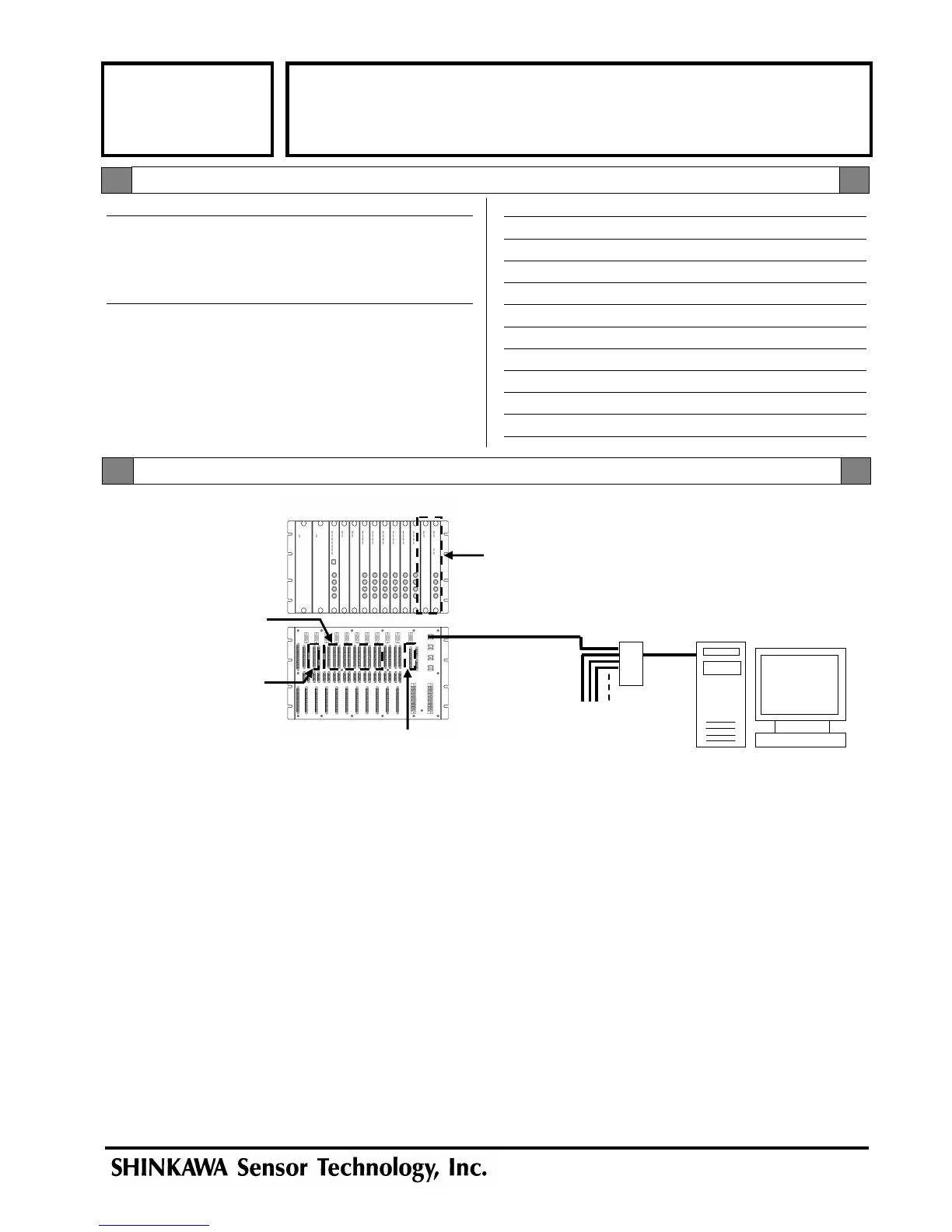
This drawing shows a typical example when modules shown in the
following are installed to a VM-761 rack.
1 unit of VM-732 Analysis module,
6 units of VM-701 Vibration / Displacement monitor module,
2 units of VM-742 Network communication module,
1 unit of VM-741 Local communication & Phase marker module,
2 units of VM-751 Power supply module.
Max. 20 rack
HUB
Vibration signal input
(Slot 3 to 8)
Phase marker signal input
(1ch, 2ch)
VM-732
Analysis Module
VM-732 ANALYSIS MODULE
Page 2of 2
VM-7 SERIES
SPECIFICATIONS
OTHERS
COMMUNICATION
IP Adress : 192.168.8.100
Subnet mask : 255.255.255.0
IP Port No. : 8882
INPUT (PHASE MARKER (3ch, 4ch))
Input points : 2 points
Input transducer : RD-05A (non-intrinsic safety)
Hysterics set value : 1V
Trigger level : -18V
Trigger mode : Manual
Default value
Phase marker signal input
(3ch, 4ch)
 Loading...