Mark VII Restored Manual - V1.02 – Donated without cost to the world-wide Shopsmith Community - Everett L. Davis 2016 11
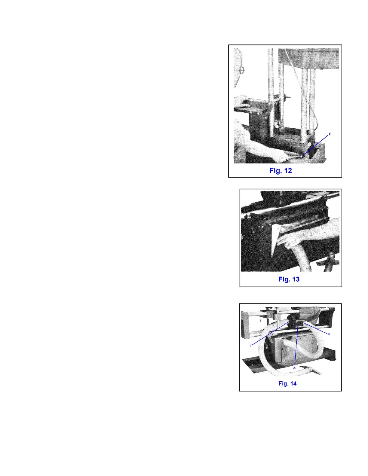
8. Adjust tilt-up stops. Unlock Trunnion on one end and tilt
machine unit to vertical on opposite end. Safety latch handles
should be pointing up.
Adjust stop screws on top of rails ("F", Fig. 12) until bed tubes are
square with stand top. Use carpenter square and sight across
tubes. Tighten stop screw jam nuts. Safety latch should now
engage lower lip of end cap. Some springing of the end frame is
normal when engaging safety latch.
Return machine to horizontal and lock trunnion. Adjust stop
screws for other end in same manner.
9. Install front panel. Return machine to horizontal and install
front panel using #6 - 32 x 1 truss head screws and Tinnerman
nuts, one each in middle on each side.
10. Install rear panel. Unfold sawdust vacuum bag and lay it on inside
of rear panel so that bag matches panel and inlet tube of bag lines up
with large flanged hole in panel. Tuck tube about one inch through
hole and spread it so that one end of the short hose can be inserted.
Make sure bag is still square with panel and secure it by pushing hose
adapter into panel hole, thereby sealing hose to bag tube. Mount rear
panel with hose at upper left corner, (Fig. 13) using the two #6 plastic
head thumb screws and Tinnerman nuts. Rest bottom of bag on rear
rail.
11. Connect discharge hose. Plug other end of hose into impeller
outlet duct opening ("G", Fig. 14). On some units the duct has two
outlets, one direct and one offset ("H"). The offset opening allows
vacuum to be used when carriage is next to headstock. Plug unused
hole with push-in plastic cap provided.
12. Connect vacuum hose. Plug long hose into impeller housing inlet
("J", Fig. 14) and your machine is ready to run.
BEFORE OPERATING YOUR SHOPSMITH MAKE THE ACCURACY CHECKS
WHICH FOLLOW IMMEDIATELY ON NEXT PAGE