Page 11-di/of 40
The pump must be hydraulically connected with PVC tubes with 50 [mm] external
diameters.Tubes must be inserted in the fittings for about 1÷2 [cm] and secured with
the supplied fast connections.
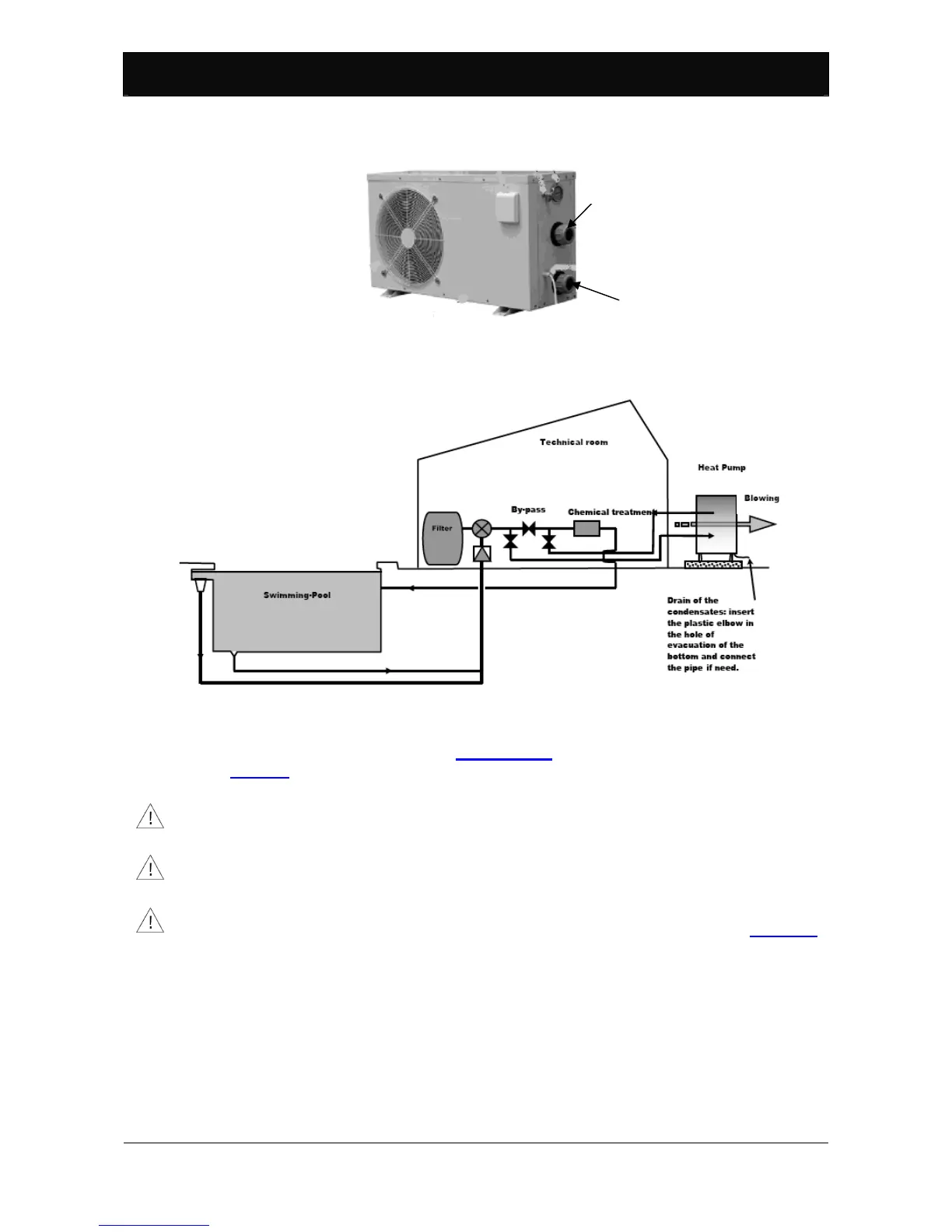
Figure 5: Hydraulic connections
The hydraulic circuit is usually created as illustrated in the following figure.
Figure 6: Typical hydraulic circuit part layout.
Minimum heat pump water input flow must not be under the value required for
the model in question. See Paragraph 2. For system layouts such as that in
Figure 6, water flow can be regulated using the bypass valve.
4.6. Electrical connections.
The heat pump electrical connections must be performed by specialised
technicians and in keeping with current national system regulations.
Working on live electrical equipment is prohibited. Before starting work, make sure
the heat pump is disconnected from the electrical mains.
Modifying electrical connections inside the heat pump without Shott International
SRL authorisation is strictly prohibited.
Electrical connections must be performed as illustrated in the wiring diagram in Figure 10.
Power voltage must not vary more than 10 % from the nominal value. It must be within the
207÷253 [V] interval. If power voltage is subject to frequent variations, contact specialised
technicians for suitable protection devices.
Install a protection device, circuit breaker with delayed type 16 [A] fuse, upstream from the
heat pump. This protection device must only service the heat pump. Furthermore, install a
contact switch protection device, circuit breaker, that has nominal operating differential
current not over 30 [mA].
Output fitting
Input fitting
 Loading...