Page 12-di/of 40
Figure 7: Protection device and/or contact switch.
The electrical mains connected to the heat pump must be grounded.
If a socket is installed for electrical mains connections, the latter must have a protection
grade no lower than IPX4 and must have a grounding terminal. The same applies for the
mains which must be grounded.
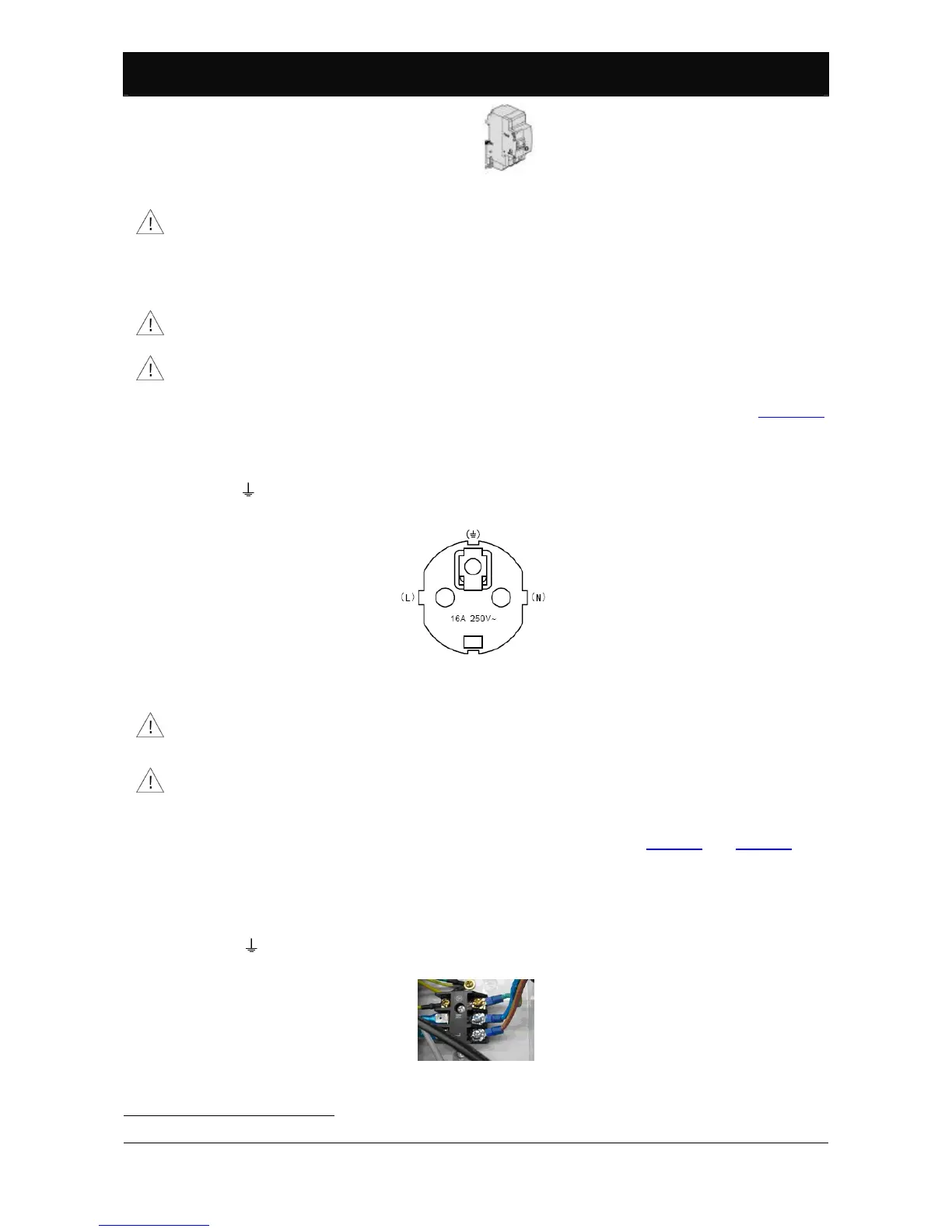
4.7. Socket installation for mains connections.
Use a socket with nominal current no lower than 16 [A] equipped with a grounding terminal
with protection grade no lower than IPX4.
Proceed as follows to install the mains connection socket:
• Make sure the heat pump is disconnected from the mains.
• Open the socket and connect the heat pump power wires to the terminals. Make sure
electrical connections observe that illustrated in the following figure, Figure 8.
Terminal names:
• L. phase conductor;
• N, neutral conductor;
• , grounding conductor.
• Close the socket.
Figure 8: Socket connection illustration.
4.8. Mains connection cord replacement.
Use a three-polar cord no lighter than an ordinary rubber sheathed flexible cord
17
, each
conductor section must not be lower than 1.5 [mm
2
].
Proceed as follows to replace the mains connection cord:
• Make sure the heat pump is disconnected from the mains.
• Remove the upper heat pump panel by unscrewing the fastening screws.
• Remove the control board protection panel by unscrewing the fastening screws.
•
Disconnect the mains connection wire from the terminals, see Figure 9 and Figure 9.
• Install the new mains connection cord using the supplied or similar raceway.
• Connect the connection cord to the electrical mains observing terminal names:
• L. phase conductor;
• N, neutral conductor;
• , grounding conductor.
• Reassemble the control board protection panel and upper panel.
Figure 9: Mains connection terminals.
17
60245 IEC 57 designation.
 Loading...