Page 13-di/of 40
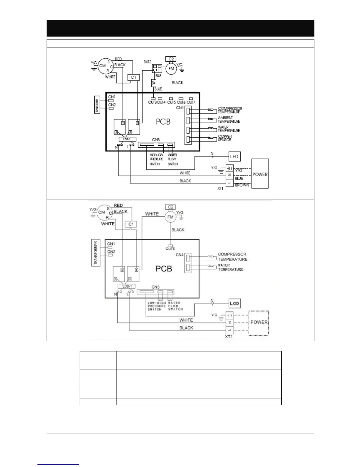
Model BP-xxHS-A (xx=50, 85, 100)
Model BP-xxWS-B (xx=35, 50).
Figure 10: Wiring diagram.
YV Four way valve
FM Fan motor
CM Compressor
PCB Control board
LDB-1 Dispersion sensor
XT1 Electrical mains connection terminals
XT2 Hub
C1 Compressor capacitor
C2 Fan capacitor
Table 1: Control board part legend.
 Loading...