Page 25-di/of 40
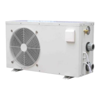
Figure 37: Ambient temperature sensor.
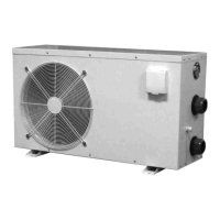
Figure 38: Pool water temperature sensor.
Temperature sensors are connected to connector CN4 (ambient temperature and
water temperature) as indicated in the wiring diagram, see Figure 10. Sensor
operations can be checked by measuring the resistance when temperature
changes. Usual values are indicated in Paragraph 6.3.
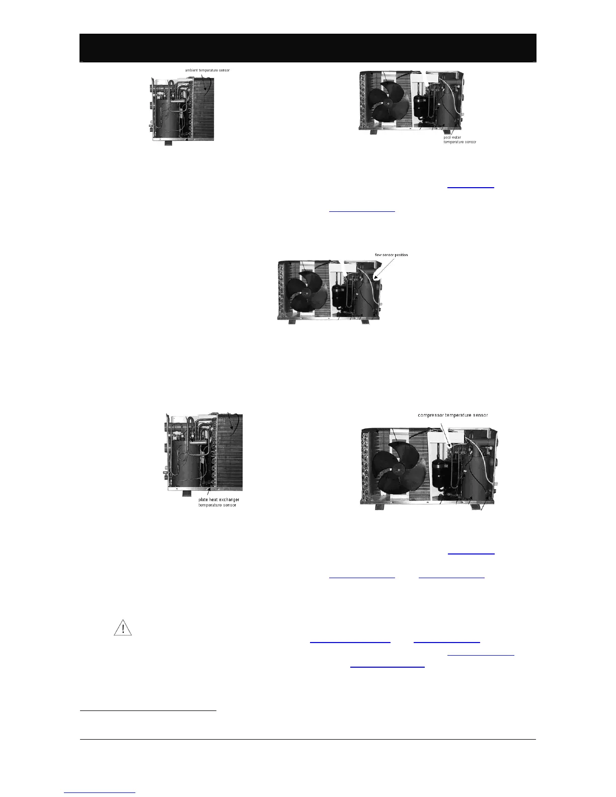
6.1.2. Flow sensor.
SERIES BP control pumps are equipped with a flow sensor that continuously reads
water flow. The sensor is located as illustrated in the following figure.
Figure 39: Flow sensor position.
6.2. Safety devices.
6.2.1. Compressor and plate heat exchanger temperature sensors
37
.
SERIES BP heat pumps are equipped with 2 temperature sensors that continuously
read compressor and plate heat exchanger temperatures. The sensors are located
as illustrated in the following figures.
Figure 40: Plate heat exchanger temperature sensor.
Figure 41: Compressor temperature sensor.
Temperature sensors are connected to connector CN4 (compressor temperature
and copper sensor) as indicated in the wiring diagram, see Figure 10. Sensor
operations can be checked by measuring the resistance when temperature
changes. Usual values are indicated in Paragraph 6.3 and Paragraph 6.4.
6.2.2. High pressure sensor.
The high pressure sensor stops the compressor when supply pressure, in the
refrigerant circuit high pressure section, exceeds the calibration value.
The high pressure sensor signal is not considered during either manual or automatic
defrost. For further information see Paragraph 5.2.10 and Paragraph 5.3.
Trigger pressure is 4.2 [bar]. After a high pressure alarm, see Paragraph 7.5, the
heat pump must be manually restarted, see Paragraph 5.2.4.
37
Not necessary in model BP-xxWS-B (xx=35, 50) since there is no plate heat exchanger defrost
process.
 Loading...