18
Hardware Description
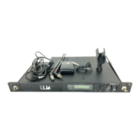
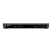
Networked Charger (NCS)
The MXW networked charging station enables battery
charging and channel linking from a single location. When
a charger is associated to a group, its channel slots are
mapped to access point audio channels. Microphones can
then be placed in the slots to Link to these channels.
Any microphone can recharge in any NCS, regardless of
Group association or network connection. Caution: When
the Link button on an associated charger is pressed, all
microphones in the charger will be mapped to channels on
an access point. This will override any previously Linked
microphones on those channels.
Model Variations
MXWNCS8
• Accepts eight boundary, bodypack, or
handheld microphones
• or four gooseneck bases
MXWNCS4
• Accepts four boundary, bodypack, or
handheld microphones
• or two gooseneck bases
MXWNCS2
• Accepts two boundary, bodypack, or
handheld microphones.
• MXW8 Gooseneck bases are not
supported on this charger
7
8
6
5
1
2
3
4
Link
Power
ௗ
① Charging Slots (USB 3.0 Type A)
Recharge and link microphones by connecting them to the
USB slots on the charger. When the charger is associated
to a group, the slots are mapped to access point channels
(See Audio Channel Assignment for details).
Note: Any microphone can charge in any charger, regardless of Group
association or network connection.
② Power LED
Illuminates green when the unit is powered on.
③ Microphone Link LED
Indicates the status of the Linking procedure:
Color Indicator
Off
(default)
No Link has been initiated.
Flashing
Green
Link procedure is in process.
Green
Microphones have been successfully
linked to channels.
Red
Link procedure unsuccessful (RF issue,
network failure, or microphones removed
during procedure)
Amber
Link procedure cannot start because the
station is not associated to a group.
Flashing
Red
Link procedure has been locked from the
control software.
④ Microphone Link Button
Press and hold for 6 seconds to link all microphones in
the charger to channels of the associated Access Point
Transceiver.
⑤ Battery Status LEDs
Monitors the charge status of the connected microphone in
increments of <10, 10, 25, 50, 75, 100% (see Batteries for
more detail). Additionally, the five LEDs flash for several
seconds when the microphone has been successfully linked
to the channel.