15
Hardware Description
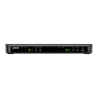
Audio Network Interface (ANI)
The ANI performs the following functions:
• Converts digital audio from the network into analog audio
to connect to a sound reinforcement system or recording
device
• Four-port gigabit switch can connect an entire MXW
system (up to eight channels) and power the MXW
access point
• Provides analog input(s) to route audio to the
microphones for personal monitoring.
• Front-panel interface provides status indicators and
access to basic system controls.
• Hosts an embedded web server that provides an interface
for monitoring and control of the device.
Model Variations
MXWANI8 Eight channel outputs; two input channels
MXWANI4 Four channel outputs; one input channel
① Input Channels
Adds analog line- or aux-level signals to the digital network.
When the device is associated to an MXW Group, inputs
are automatically routed to Linked microphone channels
(Input A to channels 1-4; Input B to 5-8).
② Output Channels
Converts digital network audio to an analog output for each
channel. When associated to an MXW group, access point
channels are automatically routed to the outputs of the ANI.
③ Channel Selector
Selects a channel to perform the following functions:
Action Function
Single Press
• Listen to that channel at the headphone jack
• Display and adjust the channel output level
and attenuation
• Monitor output signal on the level meter
Press and
Hold (3
seconds)
Mute/unmute a channel. Mute is indicated
by the mute LED.
④ Selected Channel LED
Illuminates when a channel is selected.
⑤ Signal Strength LED (sig/clip)
Indicates audio signal strength for each channel:
• Green = Normal
• Amber = Strong
• Red = Clipping (to eliminate clipping, attenuate the signal
level at the audio source)
⑥ Mute LED
Illuminates red when the channel output is muted (hold
its channel select button for 3 seconds). A muted channel
is still routed to the HEADPHONE jack for monitoring or
troubleshooting.
⑦ Input Level Selector
Set the selected channel to line- or aux-level to match the
input signal.
⑧ Output Level Selector
Set the selected channel to an output level that matches
the connecting device:
• line: +4 dBu
• aux: -10 dBV
• mic: -30 dBV
Front Panel
lockout
power
ethernet
network audio
push to solo | hold to mute
-9
-18
-24
-36
-48
-60
0
-9
-12
-18
-24
0
aux
mic
adjust
line
sig/clip
mute
INPUT
A
sig/clip
mute
OUTPUT
HEADPHONE
Audio Network Interface
MICROFLEX WIRELESS
B
1
2
3
4
5
6
7
8
line
aux
ௗ
ௗ