Operating Instructions Chapter 5
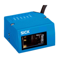
CLV62x Bar Code Scanner
Installation
8011965/S345/2008-04-16 © SICK AG · Division Auto Ident · Germany · All rights reserved 39
5.4 Installation of the bar code scanner
5.4.1 Installing the bar code scanner
1. Preparing base for the installation of the bar code scanner holder, see chapter 5.2.2
Accessories, page 34.
2. Place the object with the bar code at the designated position where the reading should
be taken in the bar code scanner's visual range (no conveyor movement).
3. Visually align the bar code scanner to the bar code. Pay attention to the following
points:
– With the bar code scanner with the front reading window, ensure that the narrow re-
verse side of the device with the laser warning sign is facing the viewer and is ap-
proximately parallel to the bar code plane.
– With the bar code scanner with the side reading window, ensure that the wide side
panel with the LEDs is facing the viewer and is approximately parallel with the bar
code plane.
– During the reading, consider the reading angle, see chapter 5.3.3 Angle alignment
of the bar code scanner, page 37.
– If the bar code's position within the scanning line is relevant for the evaluation, ob-
serve the reading angle's counting direction, see chapter 5.3.5 Counting direction
of the reading angle (position of the bar code along the scanning line), page 38.
4. Installing the bar code scanner holder on the base.
5. Screw M5 bolts through the holder and into the bar code scanner's blind hole taps and
gently tighten them.
6. Adjusting the bar code scanner, see chapter 7.6.1 Adjusting the bar code scanner,
page 63.
Damage to the device!
The maximum thread reach of the two blind hole taps M5 is 5 mm (0.2 in). Longer bolts will
damage the device.
¾ Use bolts of a suitable length.

 Loading...