Chapter 6 Operating Instructions
CLV62x Bar Code Scanner
54 © SICK AG · Division Auto Ident · Germany · All rights reserved 8011965/S345/2008-04-16
Electrical installation
6.5 Pin assignment and wire colour assignment of the
assembled cables
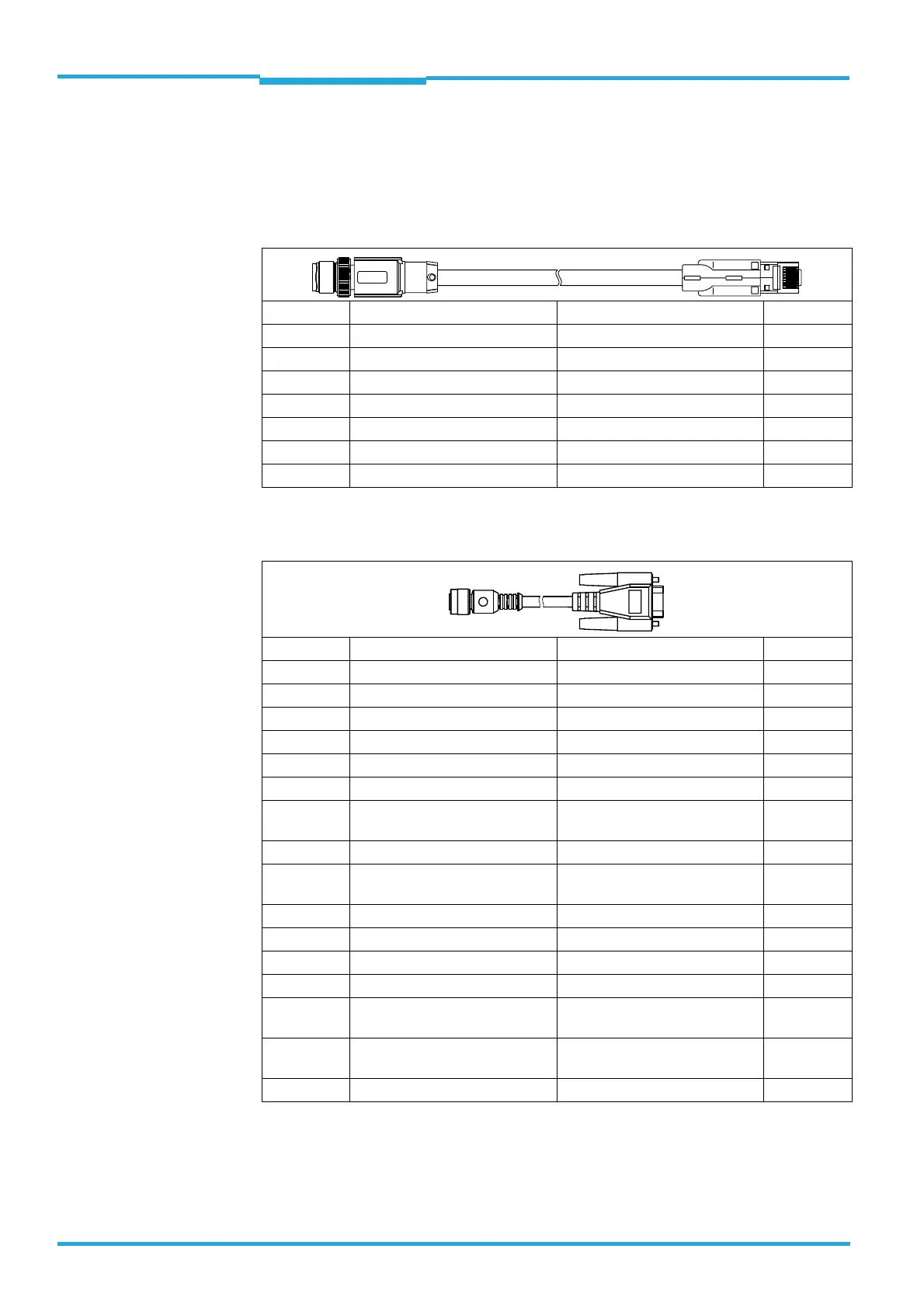
6.5.1 Pin assignment of the assembled cables
Cable no. 6034414, 6029630, 6034415, 6030928 (Ethernet version)
Tab. 6-9: Pin assignment of the 4-pole M12 plug and the 6-pole RJ45 plug
Cable no. 2042916, 2041834, 2042914, 2042915 (Ethernet version)
Tab. 6-10: Pin assignment of the 12-pole M12 socket and the 15-pole D-Sub-HD plug
Pin (4-pole) Signal Function Pin (6-pole)
1 TD+ Transmitter+ 1
3 TD- Transmitter- 2
2RD+ Receiver+ 3
--4
--5
4RD- Receiver- 6
-- Shield -
Pin (12-pole) Signal Function Pin (15-pole)
2 10 ... 30 V DC Operating voltage 1
8 RxD (Aux) Aux interface (receiver) 2
7 TxD (Aux) Aux interface (sender) 3
-- - 4
1GND Ground 5
11 RD+ (RS-422/485) Host interface (receiver) 6
12 RD– (RS-422/485);
RxD (RS-232)
Host interface (receiver) 7
5 TD+ (RS-422/485) Host interface (sender) 8
6 TD– (RS-422/485);
TxD (RS-232)
Host interface (sender) 9
4 CAN H CAN bus (IN/OUT) 10
3 CAN L CAN bus (IN/OUT) 11
-- - 12
-- - 13
10 Sensor 1 Digital switching input for exter-
nal reading pulse
14
9 SensGND Common ground for the switching
inputs
15
-– Shield -

 Loading...


