Chapter Operating Instructions
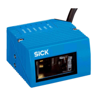
CLV62x Bar Code Scanner
6 © SICK AG · Division Auto Ident · Germany · All rights reserved 8011965/S345/2008-04-16
Figures and Tables
Tables
Tab. 1-1: Target group ........................................................................................................9
Tab. 2-1: Required qualification for starting up the bar code scanner ........................ 11
Tab. 2-2: Laser Data of CLV62x ...................................................................................... 14
Tab. 4-1: CLV62x Bar Code Scanner delivery ................................................................ 23
Tab. 4-2: Variants of the CLV62x Bar Code Scanner .................................................... 24
Tab. 4-3: Overview of the bar code scanner's product features and functions ........... 26
Tab. 4-4: Data interface function .................................................................................... 30
Tab. 4-5: LED indications ................................................................................................. 32
Tab. 5-1: Permitted reading angles between the scanning line and bar code ............ 37
Tab. 6-1: Electrical connections to the bar code scanner with a fixed cable and
connector (standard version) .......................................................................... 45
Tab. 6-2: Electrical connections to the bar code scanner with connector unit
(Ethernet version) ............................................................................................ 45
Tab. 6-3: Standard version: Pin assignment of the 15-pole D-Sub-HD cable
connector .......................................................................................................... 46
Tab. 6-4: Ethernet version: Pin assignment of the 4-pole M12 socket ....................... 46
Tab. 6-5: Ethernet version: Pin assignment on the 12-pole M12 plug ........................ 47
Tab. 6-6: Recommended maximum cable lengths, depending on the selected
data transfer rate ............................................................................................. 49
Tab. 6-7: Ratings for the switching inputs ..................................................................... 52
Tab. 6-8: Ratings for the switching outputs ................................................................... 53
Tab. 6-9: Pin assignment of the 4-pole M12 plug and the 6-pole RJ45 plug .............. 54
Tab. 6-10: Pin assignment of the 12-pole M12 socket and the 15-pole
D-Sub-HD plug .................................................................................................. 54
Tab. 6-11: Pin assignment of the 12-pole M12 socket and wire colours at the
open end ........................................................................................................... 55
Tab. 6-12: Pin assignment of the 5-pole M12 plug and wire colours at the open end . 55
Tab. 6-13: Pin assignment of the 15-pole D-Sub-HD socket and wire colours at
the open cable end .......................................................................................... 56
Tab. 7-1: Default setting for the SOPAS-ET configuration software (excerpt) ............. 58
Tab. 7-2: Connection between the PC with SOPAS-ET configuration software and
the bar code scanner ....................................................................................... 58
Tab. 10-1: Technical specifications for the CLV62x Bar Code Scanner
(line/raster scanner)......................................................................................... 72
Tab. 10-2: Reading conditions for all specification diagrams ........................................ 73
Tab. 11-1: Help table for calculating the code length of a bar code ............................... 84
Tab. 11-2: Variants of the CLV62x Bar Code Scanner .................................................... 85
Tab. 11-3: In stock accessories: Installation accessories................................................ 86
Tab. 11-4: In stock accessories: Connection modules..................................................... 87
Tab. 11-5: In stock accessories: Extensions for connection modules ............................ 89
Tab. 11-6: In stock accessories: Separate field bus modules ......................................... 89
Tab. 11-7: In stock accessories: Cables and connectors for the standard version
of the bar code scanner ................................................................................... 90
Tab. 11-8: In stock accessories: Cables and connectors for the Ethernet version
of the bar code scanner ................................................................................... 90
Tab. 11-9: In stock accessories: General cables and connectors for
bar code scanner .............................................................................................. 92
Tab. 11-10: Supplementary documentation ....................................................................... 96

 Loading...