1
2
3
4
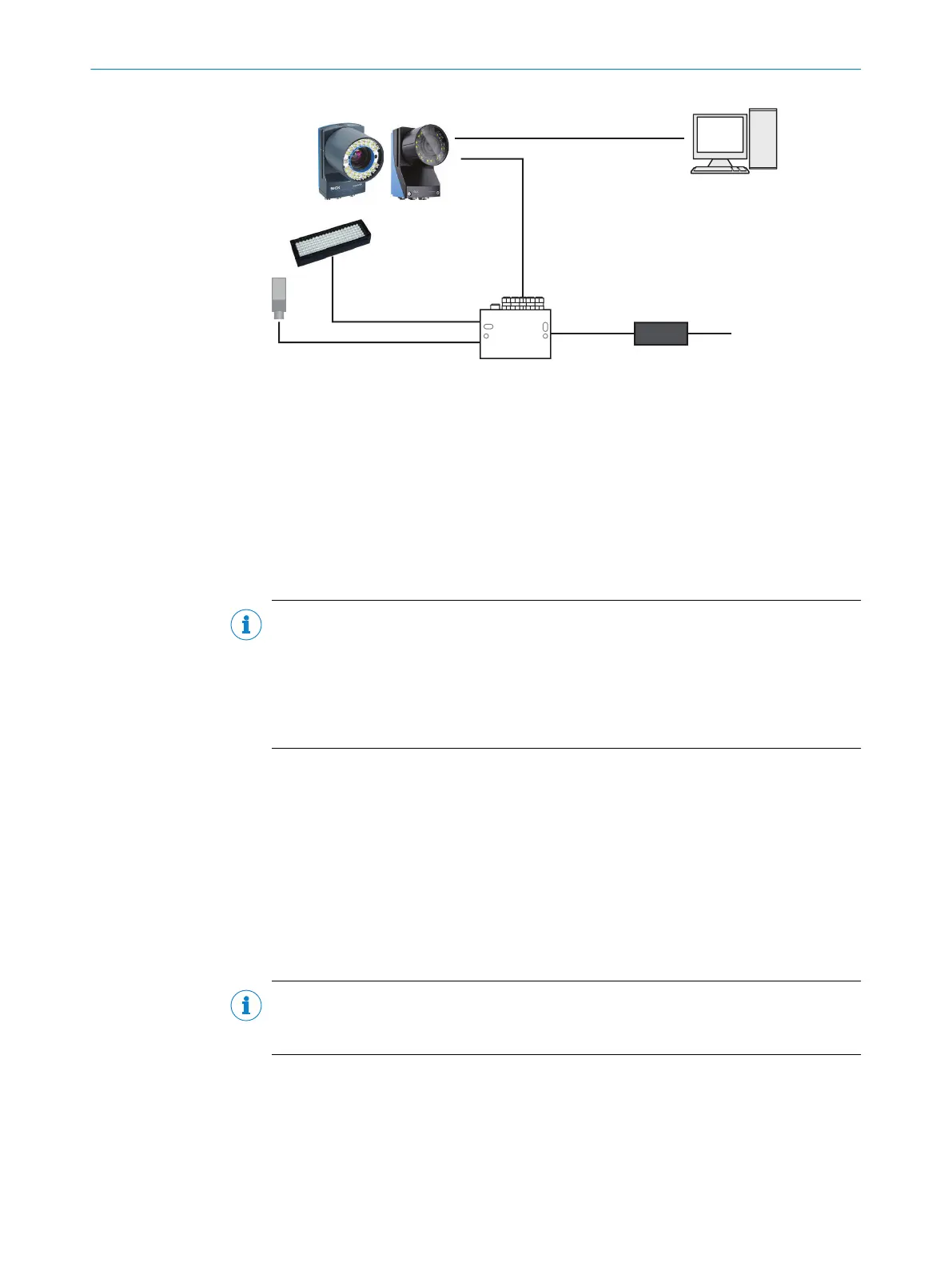
Inspector8xx
Voltage supply
24 V DC
External
illumination
Photoelectric sensor
Computer with Gigabit
Ethernet interface
Connection module,
i.e. CDB650
Ethernet or USB-C cable
Power I/O cable
5
6
7
Figure 5: Connecting an Inspector8xx
1
Ethernet or USB-C cable
2
Power I/O cable
3
Computer with Gigabit Ethernet interface
4
Voltage supply 24 V DC
5
Connection module, i.e. CDB650
6
External illumination
7
Photoelectric sensor
NOTE
Preset IP addresses of the Ethernet interfaces:
•
Ethernet (default): 192.168.0.1
•
USB-C: 169.254.0.1
When using USB-C, you can usually access the device at 169.254.0.1 without any
configuration.
Further topics
•
Electrical installation
•
Setting up the Ethernet network
•
Setting up the USB interface
4.3 Setting up the Ethernet network
The Ethernet network must be correctly set up, in order for the computer and device
to communicate. The Ethernet network can be a factory or office network, or consist of
only the computer and the device.
NOTE
Both the computer and the device must be set up for communication on the same
network.
In this example, we connect the device directly to a Windows computer. The network
consists of the computer, the device, and the Ethernet cable between them. Set the
IP address and the Subnet mask so that each device has a unique IP address. The IP
address must still be similar enough to belong to the same network.
4 GETTING STARTED
22
O P E R A T I N G I N S T R U C T I O N S | Inspector83x 8029044/1MYO/2024-04 | SICK
Subject to change without notice