7.3 Connections and pin assignment
Overview
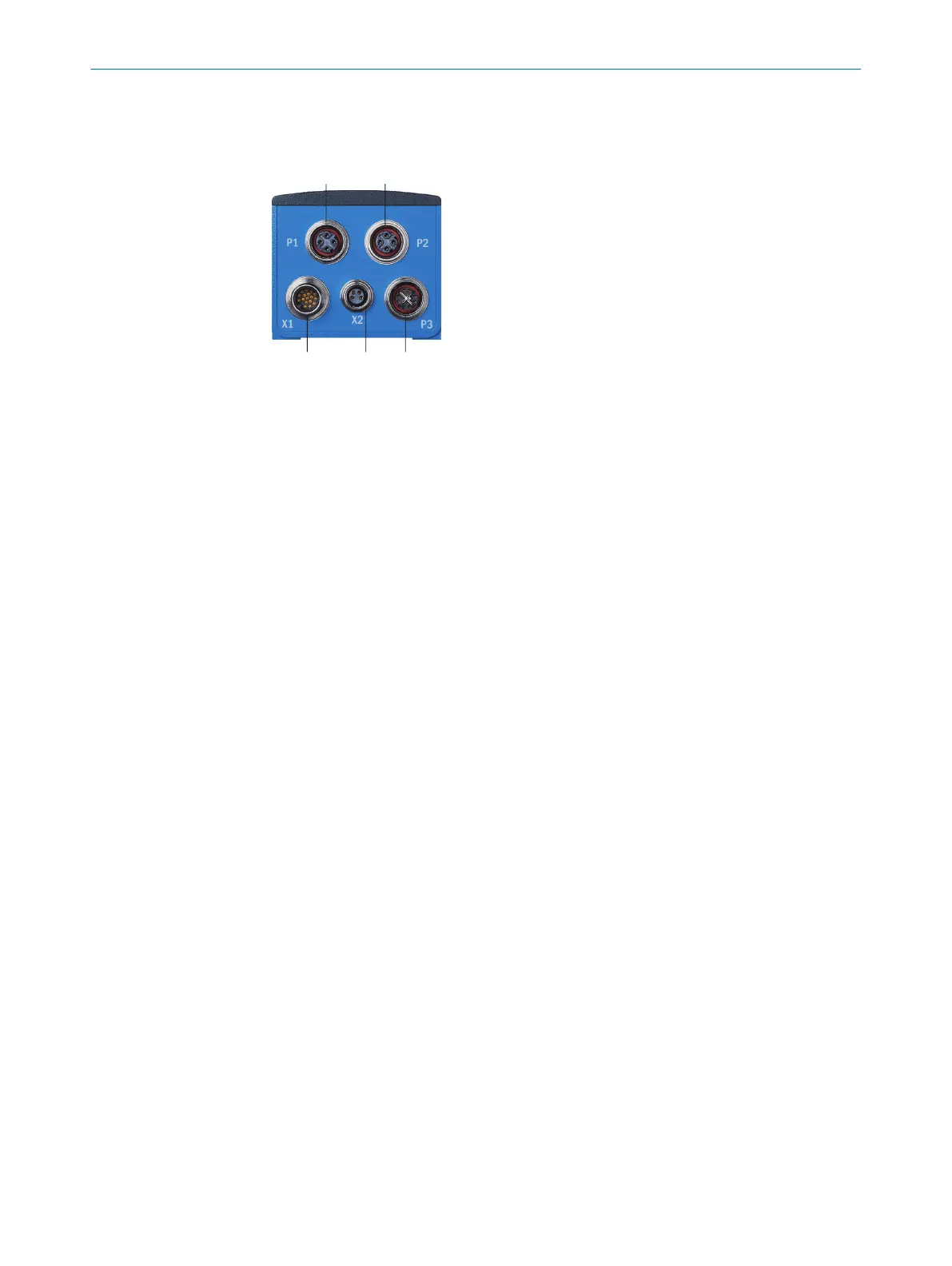
Figure 11: Connection overview
1
P1: Fieldbus Ethernet 1
2
P2: Fieldbus Ethernet 2
3
P3: GB Ethernet
4
X2: External illumination/IO
5
X1: Power/serial interface/IO
Important information
Prerequisites
General
•
Connect the connecting cables in a de-energized state. Do not switch on the sup‐
ply voltage until installation is complete and all connecting cables are connected
to the device and control.
•
Wire cross-sections in the supply cable from the user’s power system must be
implemented in accordance with the applicable standards.
•
In the case of open end cables, make sure that bare wire ends do not touch. Wires
must be properly insulated from each other.
•
The maximum current consumption depends on how the product is used. If out‐
puts are used, the current consumption will be higher. Ensure that the sum of the
output currents at the outputs does not exceed 400mA.
Data cables
•
Use shielded data cables with twisted-pair wires.
•
Implement proper and complete shielding concept.
•
To avoid interference, always use EMC-compliant cables and layouts. This applies,
for example, to cables for switched-mode power supplies, motors, clocked drives,
and contactors.
•
Do not lay cables over long distances in parallel with voltage supply cables and
motor cables in cable ducts.
Voltage supply
•
Configure the circuits connected to the device as ES1 circuits or as SELV circuits
(SELV = Safety Extra Low Voltage). The voltage source meets the requirements of
ES1 (EN62368-1) or SELV (EN60950-1).
•
The device must be supplied with an energy-limited source as per UL61010-1, 3rd
ed. cl. 9.4 or a limited current source as per UL62368-1 or Class 2 as per NEC.
•
Required power output of the voltage source: at least 48W
ELECTRICAL INSTALLATION
7
8029044/1MYO/2024-04 | SICK O P E R A T I N G I N S T R U C T I O N S | Inspector83x
37
Subject to change without notice