•
For a supply voltage of DC 24V ±20%, protect the cables with a separate fuse.
The type of fuse required depends on the cable used (typically cable M12 17-pin
with 2A fuse). Install the fuse in the supply circuit at the start of the supply cable.
•
To ensure protection against short-circuits/overload in the customer’s supply
cables, choose and implement wire cross-sections in accordance with the appli‐
cable standards.
Power/serial interface/IO
1
2
6 714
12
3
4
5
8
9
10
11
13
15
17
16
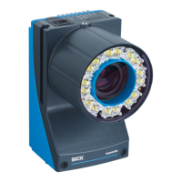
Figure 12: Male connector, M12, 17-pin, A-coded
PIN Signal Function
1 GND Ground
2 V
S
Supply voltage: DC 24V ±20%
3 – –
4 – –
5 TD+ (RS-422) Serial data interface (sender+)
6 TD- (RS-422)
TxD (RS-232)
Serial data interface (sender-)
7 TxD (RS-232) Serial service interface (sender)
8 RxD (RS-232) Serial service interface (receiver)
9 SensGND Ground digital inputs 1 and 2
10 Sensor 1 Digital input 1 (insulated)
11 RD+ (RS-422) Serial data interface (receiver+)
12 RD- (RS-422)
RxD (RS-232)
Serial data interface (receiver–)
13 IN/OUT 3 Digital input/output 3 (configura‐
ble)
14 IN/OUT 4 Digital input/output 4 (configura‐
ble)
15 Sensor 2 Digital input 2 (insulated)
16 IN/OUT 5 Digital input/output 5 (configura‐
ble)
17 IN/OUT 6 Digital input/output 6 (configura‐
ble)
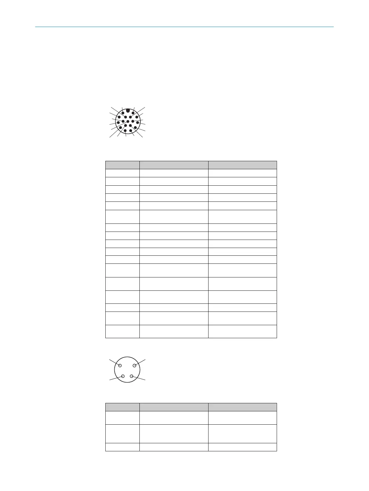
External illumination/IO
Figure 13: Female connector, M8, 4-pin
PIN Signal Description
1 V
out
switchable
1)
2)
Switchable power out for external
illumination
2 IN/OUT 7 or Trigger external illumi‐
nation
Digital input/output (configurable)
or
Trigger for external illumination
3 GND Ground
7 ELECTRICAL INSTALLATION
38
O P E R A T I N G I N S T R U C T I O N S | Inspector83x 8029044/1MYO/2024-04 | SICK
Subject to change without notice