6 Mounting
6.1 Mounting instructions
•
Observe the technical data.
•
To prevent condensation, avoid exposing the device to rapid changes in tempera‐
ture.
•
The mounting site has to be designed for the weight of the device.
•
Mount the product in a shock and vibration insulated manner.
6.2 Mounting the lens and illumination unit
Overview
This mounting step is only required for the Inspector83x Flex product variant (basic
device).
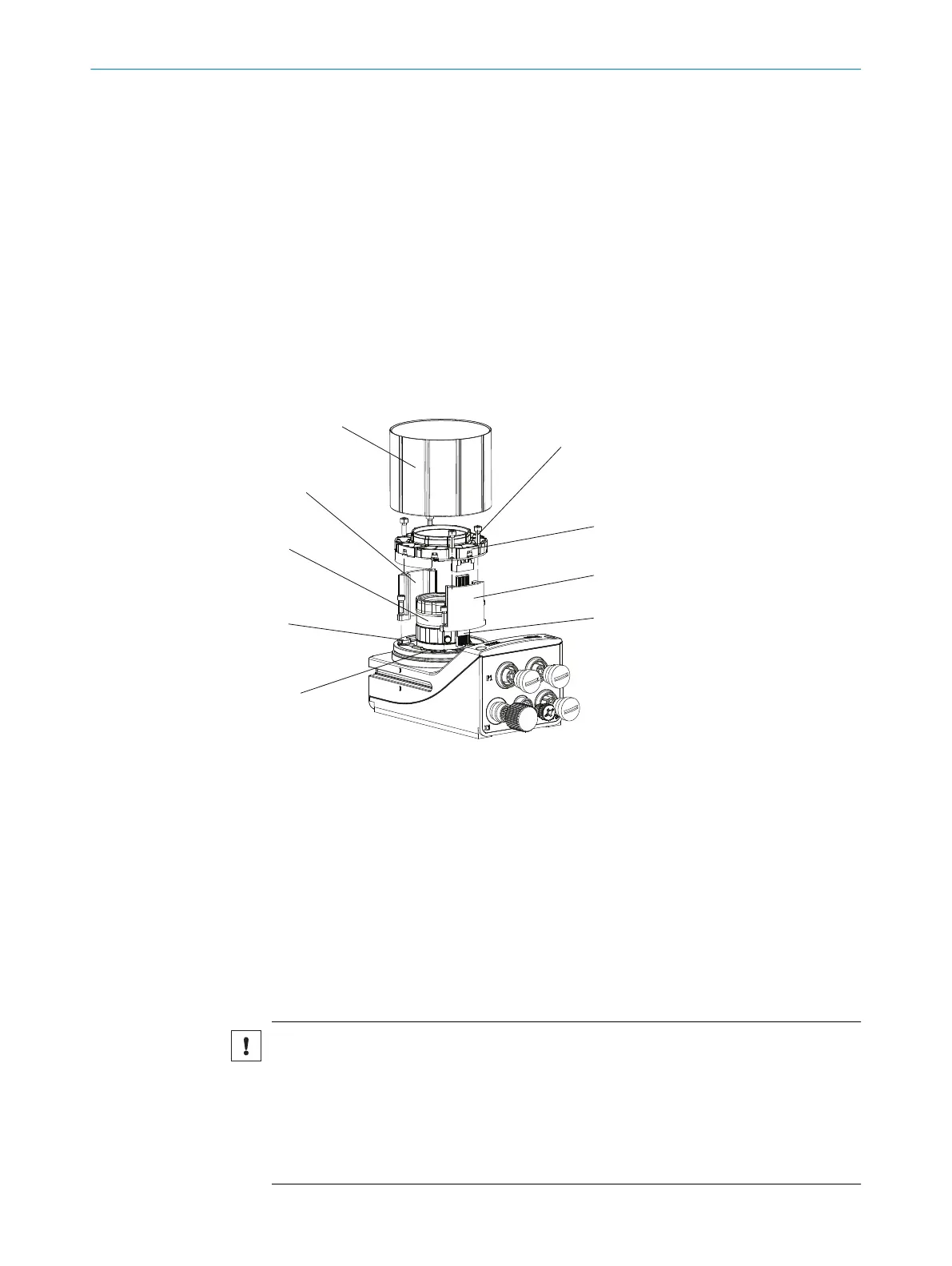
Figure 7: Mounting the lens and illumination unit
1
Light inlet with threaded connection for the lens
2
4 tapped blind holes, M2.5, 6.2 mm deep, for mounting the spacer
3
Lens
4
Spacer, top
5
Optics protective hood
6
4 holes and screws for mounting the illumination
7
Integrated illumination unit
8
Spacer, bottom
9
Electrical connection for the integrated illumination unit
Important information
NOTICE
Risk of damage due to electrostatic discharge
Electrostatic discharge from the human body may damage parts of the illumination unit
or the camera housing.
■
Take the necessary ESD precautions when assembling the device.
■
Do not touch the open contacts of the electrical connection on the camera hous‐
ing and the illumination unit.
MOUNTING 6
8029044/1MYO/2024-04 | SICK O P E R A T I N G I N S T R U C T I O N S | Inspector83x
29
Subject to change without notice