PIN Signal Description
4 IN/OUT 8 or Trigger external illumi‐
na
tion
Digital input/output (configurable)
or
Trigger for external illumination
1)
The maximum output current is configurable and fused internally with a self-resetting fuse:
•
1.0A
•
0.2A
2)
The internal illumination is shut off when the power out via X2 connector is enabled depending on the
f
use:
•
1.0A: Internal illumination shut off
•
0.2A: Internal illumination available
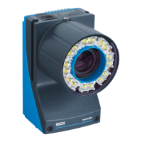
Fieldbus Ethernet
Figure 14: Female connector, M12, 4-pin, D-coded
PIN Signal Description
1 TX+ Sender+
2 RX+ Receiver+
3 TX– Sender–
4 RX– Receiver–
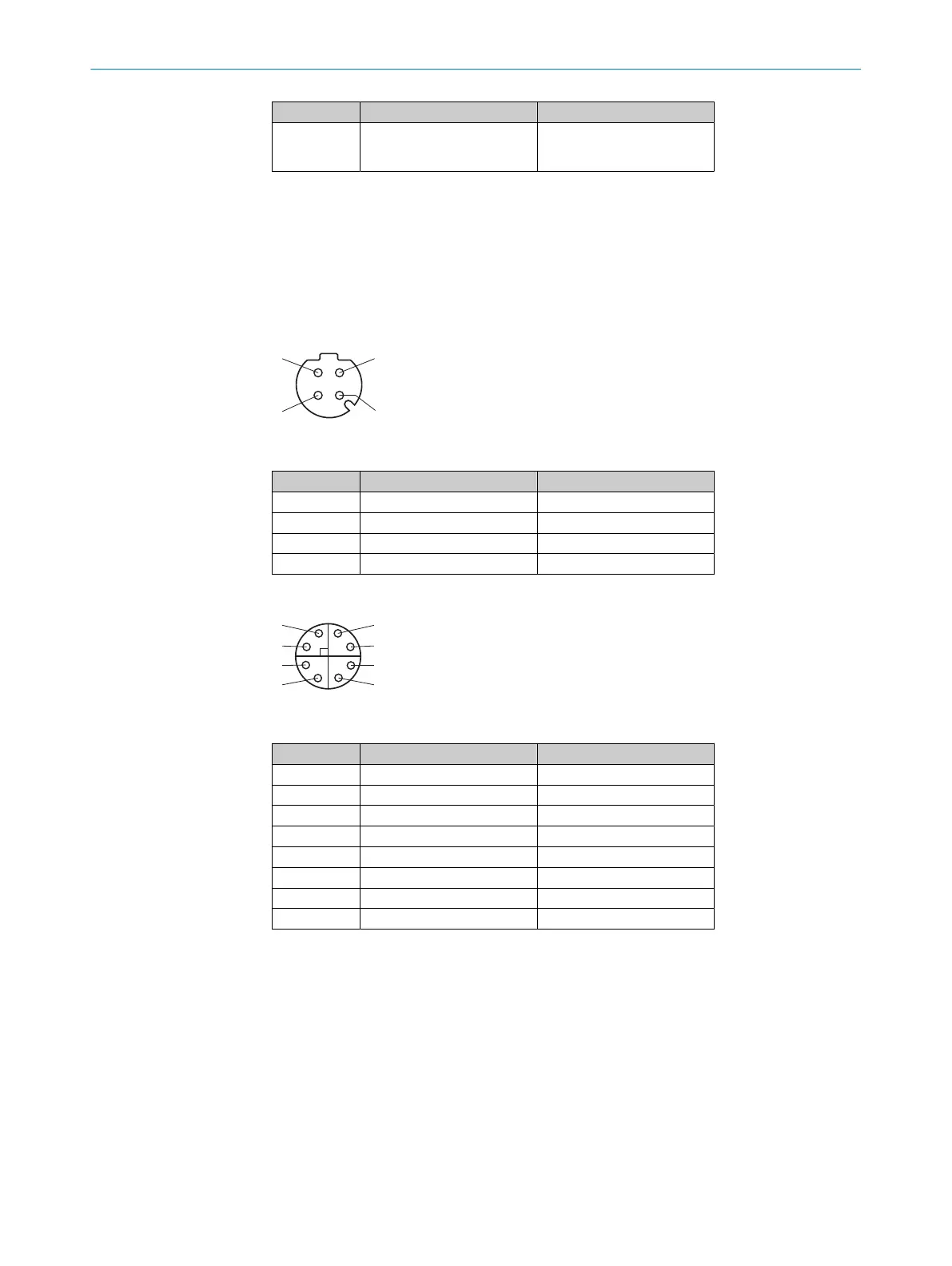
GB Ethernet
Figure 15: Female connector, M12, 8-pin, X-coded
PIN Signal Description
1 TRD0_P Sender+/receiver+ 0
2 TRD0_N Sender–/receiver– 0
3 TRD1_P Sender+/receiver+ 1
4 TRD1_N Sender–/receiver– 1
5 TRD3_P Sender+/receiver+ 3
6 TRD3_N Sender–/receiver– 3
7 TRD2_N Sender–/receiver– 2
8 TRD2_P Sender+/receiver+ 2
Complementary information
Pr
e-assembled cables can be found on the product page.
The call is made via the SICK Product ID: pid.sick.com/{P/N}/{S/N}
{P/N} corresponds to the part number of the product, see type label.
{S/N} corresponds to the serial number of the product, see type label (if indicated).
Further topics
•
Inf
ormation on interfaces: Technical data
ELECTRICAL INSTALLATION 7
8029044/1MYO/2024-04 | SICK O P E R A T I N G I N S T R U C T I O N S | Inspector83x
39
Subject to change without notice