•
The dimensions of the field of view for a certain working distance and lens focal
length
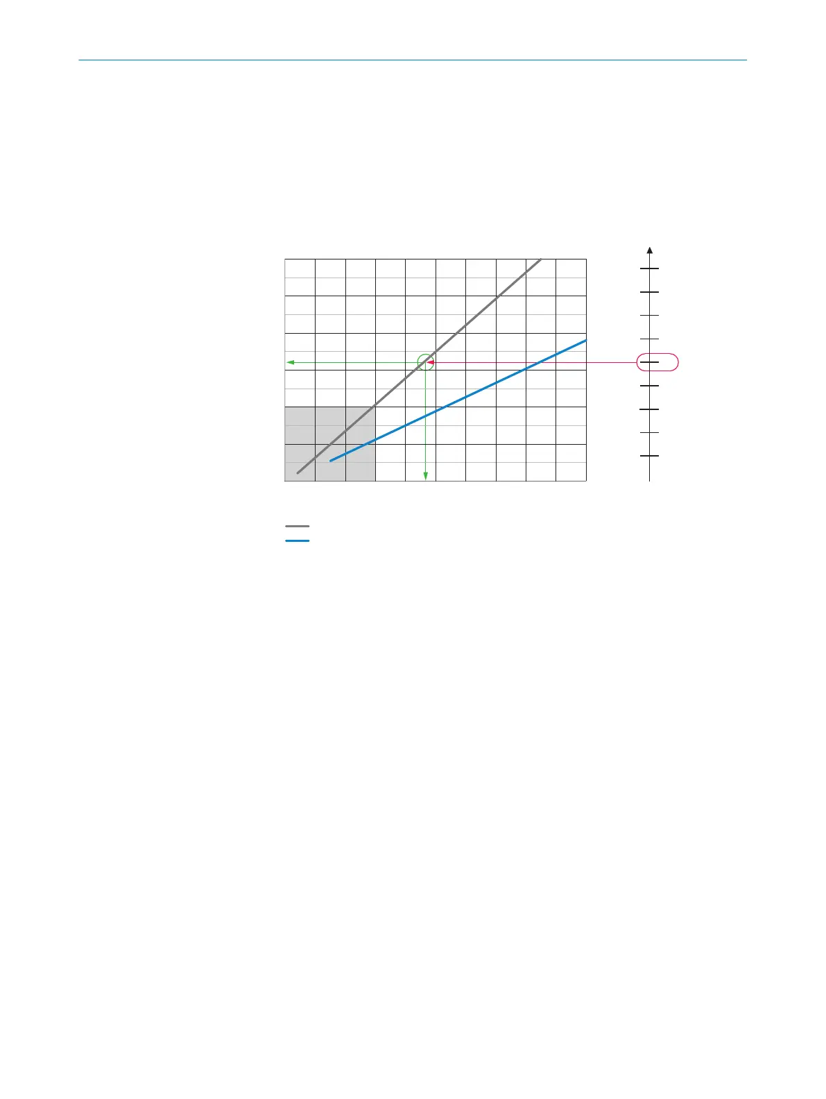
Interpretation aid for the field of view diagram
Using the diagram, you can determine the following data for each device type:
•
The maximum working distance for a selected resolution
•
The dimensions of the field of view that is available for this distance
a: f = 9.6 mm
b: f = 17.1 mm
0
200 x 160
400 x 320
600 x 480
800 x 640
1000 x 800
1200 x 960
0 200 400 600 800 1000 1200 1400 1600 1800 2000
a
b
0.1
0.3
0.5
0.6
0.7
0.8
0.9
Working distance/focus position (mm) 4
Field of view: H x V (mm) 1
Complete area 2
5
0.4
0.2
Approx. resolution (mm/px) 3
6
7
8
Figure 18: Example of field of view diagram
1
Field of view: horizontal x vertical in mm
2
Complete area
3
Approximate resolution in mm/px
4
Working distance/Focus position in mm
5
Selected resolution
6
Focal length of lens, here example for f = 9.6mm
7
Reading off: resultant maximum working distance
8
Reading off: resultant field of view (mm x mm)
Given (in red):
•
Resolution 5: approx. 0.5mm/px
•
Focal length of lens 6: 9.6mm
Read off (in green):
•
Maximum working distance 7: approx. 930mm
•
Field of view 8: approx. 640mm x approx. 510mm
Both axes of the diagrams must be interpreted linearly.
12
TECHNICAL DATA
54
O P E R A T I N G I N S T R U C T I O N S | Inspector83x 8029044/1MYO/2024-04 | SICK
Subject to change without notice