Switching behavior PNP switching to supply voltage V
S
Default settings in the device: no function, logic: not inverted (active
high)
Properties
•
Short-circuit protected + temperature protected
•
Not electrically isolated from the supply voltage V
S
Electrical values 0 V ≤ V
out
1)
≤ V
S
(V
S
−1.5 V) ≤ V
out
≤ V
S
bei I
out
2)
≤ 100 mA
1)
Output voltage
2)
Output current
NOTE
Assign the functions for the digital outputs in the device using a configuration tool, e.g.
the configuration software SOPAS ET.
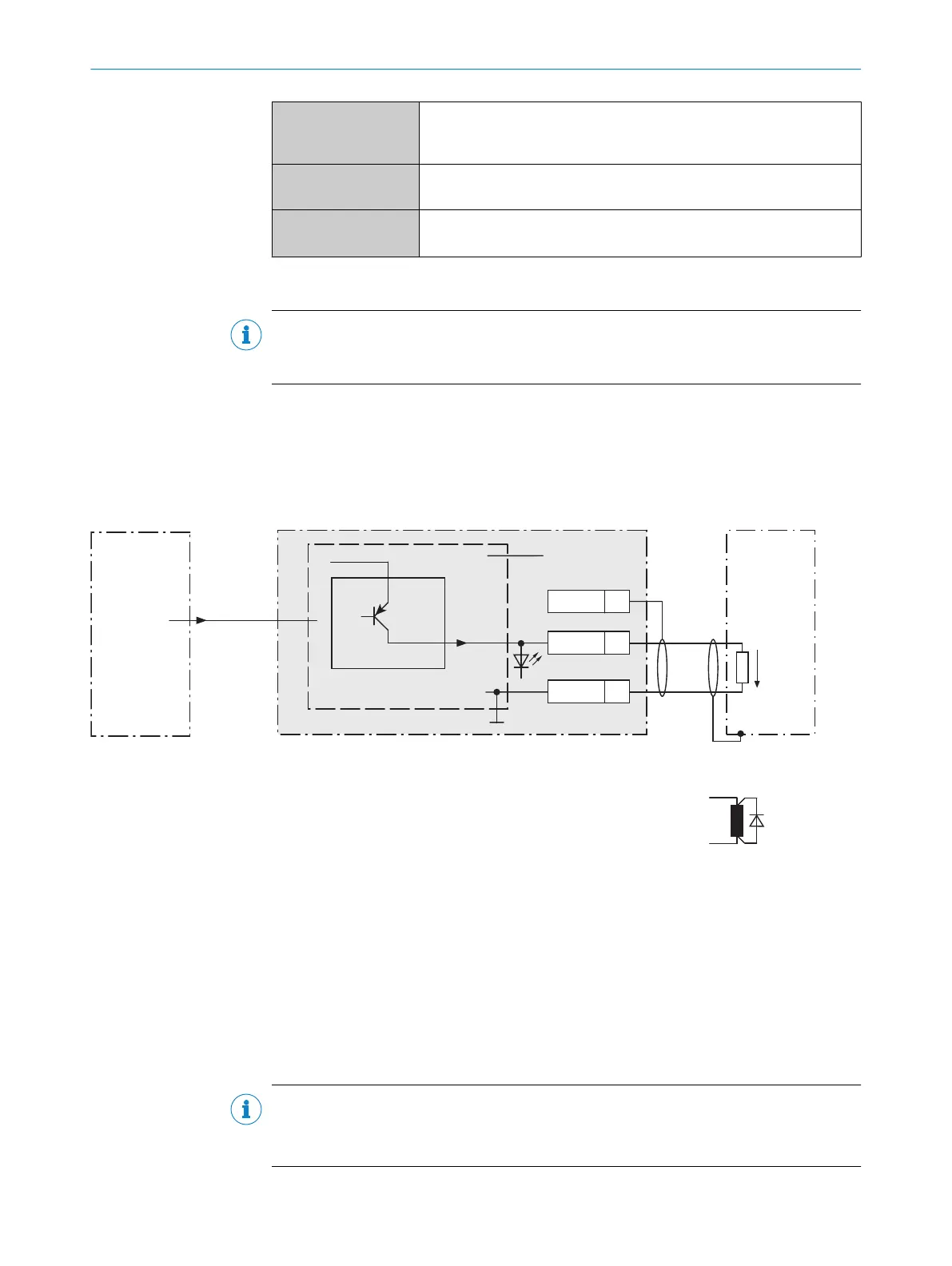
13.6.10 Wiring digital outputs “External output 1” and “External output 2” of the device in the CDB620-001
Device = Lector621 ECO = V2D621x-xxxxxYx (serial variant, Y = D or E)
Load (e.g. PLC) 4
GND
V
out
For inductive load: 6
Device 1
Aux
(RS-232)
CDB620-001
CMC600 3
U
IN
*
“External
output A” 2
C
Out B
22
GND
6
Shield
5
Figure 72: Wiring external digital outputs “Out 1” and “Out 2” of the device in the connection module CDB620-001
1
Device
2
Logical “External output” in the device
3
The optional CMC600 parameter cloning module is required in the connection module in order to be able to use the
additional external digital inputs and outputs of the device
4
Load (e.g. PLC)
5
Output voltage V
out
6
With inductive load: see note
Inductive load
NOTE
Provide an arc-suppression switch at the digital output if inductive load is present.
b
Attach a freewheeling diode directly to the load for this purpose.
ANNEX 13
8022502/15NT/2020-02-11 | SICK O P E R A T I N G I N S T R U C T I O N S | Lector621
115
Subject to change without notice