Device = Lector621 ECO = V2D621x-xxxxxYx (serial variant, Y = D or E)
Device 1
CDM420-0001
Load (e.g. PLC) 4
B
5
.
.
.
D
Result C
13
GND
5
Shield
+24 V* (V
S
)
V
S
GND
V
out
Result A
GND
1
For inductive load: 6
5
2
7
110
15
6
11
5
Cable 3
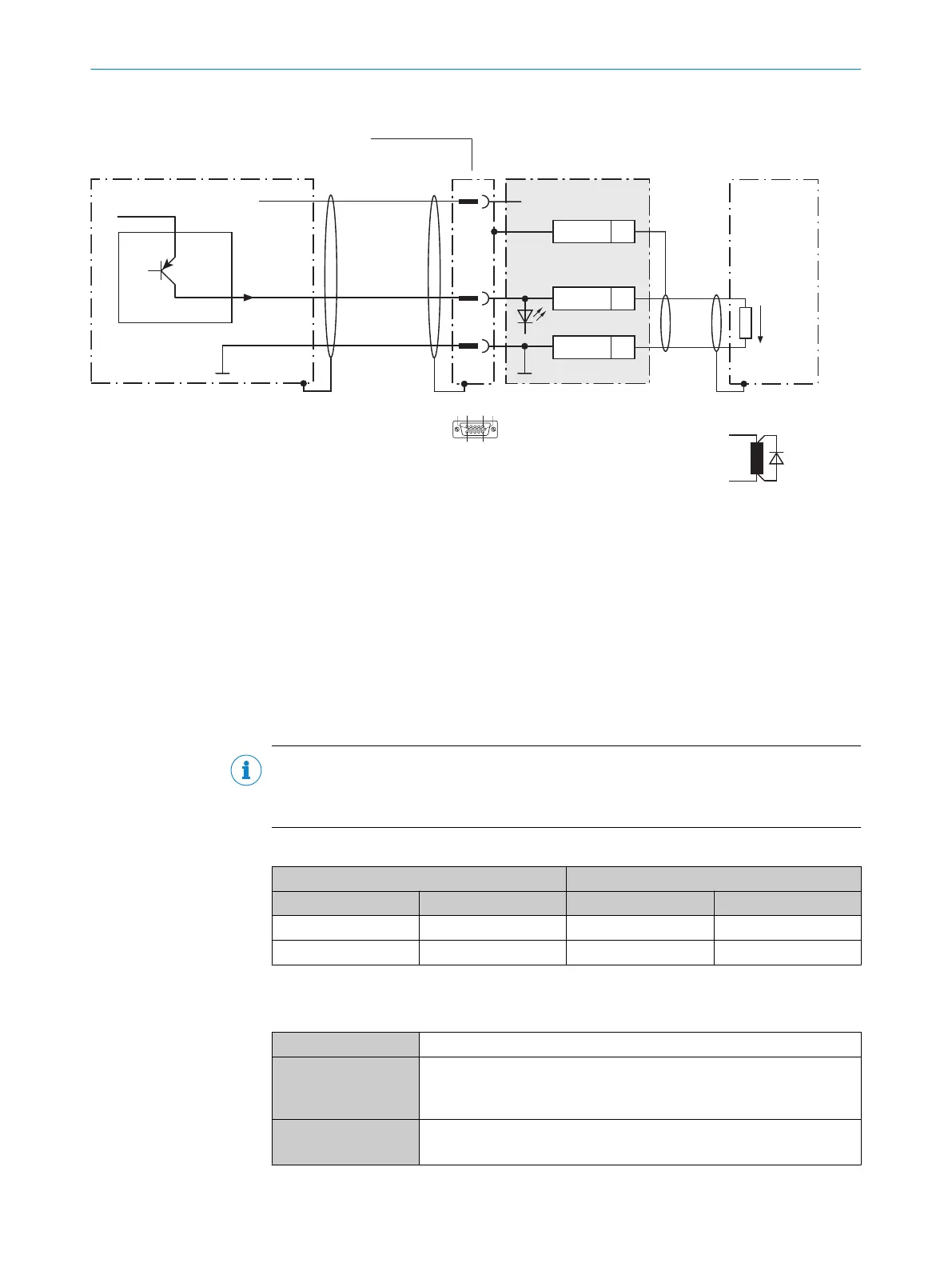
Figure 83: Wiring the digital outputs “Result 1” and “Result 2” of the device in the connection module CDM420-0001
1
Device
2
Supply voltage V
S
3
Connecting cable permanently connected with the device (male connector, D-Sub-HD, 15-pin)
4
Load (e.g. PLC)
5
Output voltage V
out
6
With inductive load: see note
7
Connection module: female connector, D-Sub-HD, 15-pin
Inductive load
NOTE
Provide an arc-suppression switch at the digital output if inductive load is present.
b
Attach a freewheeling diode directly to the load for this purpose.
Table 75: Assignment of placeholders to the digital outputs
Device CDM420-0001
Output A Pin B Signal C Terminal D
Result 1 13 Result 1 14
Result 2 14 Result 2 15
Characteristic data of the digital outputs
Table 76: Characteristic data of the digital outputs “Result 1” and “Result 2”
Type Switching
Switching behavior SPNP switching to supply voltage V
S
Default settings in the device: no function, logic: not inverted (active
high)
Properties
•
Short-circuit protected + temperature protected
•
Not electrically isolated from the supply voltage V
S
ANNEX 13
8022502/15NT/2020-02-11 | SICK O P E R A T I N G I N S T R U C T I O N S | Lector621
127
Subject to change without notice