1
Trigger sensor, e.g. for read cycle generation
2
External supply voltage V
S ext
3
Input voltage V
in
4
PNP sensor
5
Supply voltage V
S
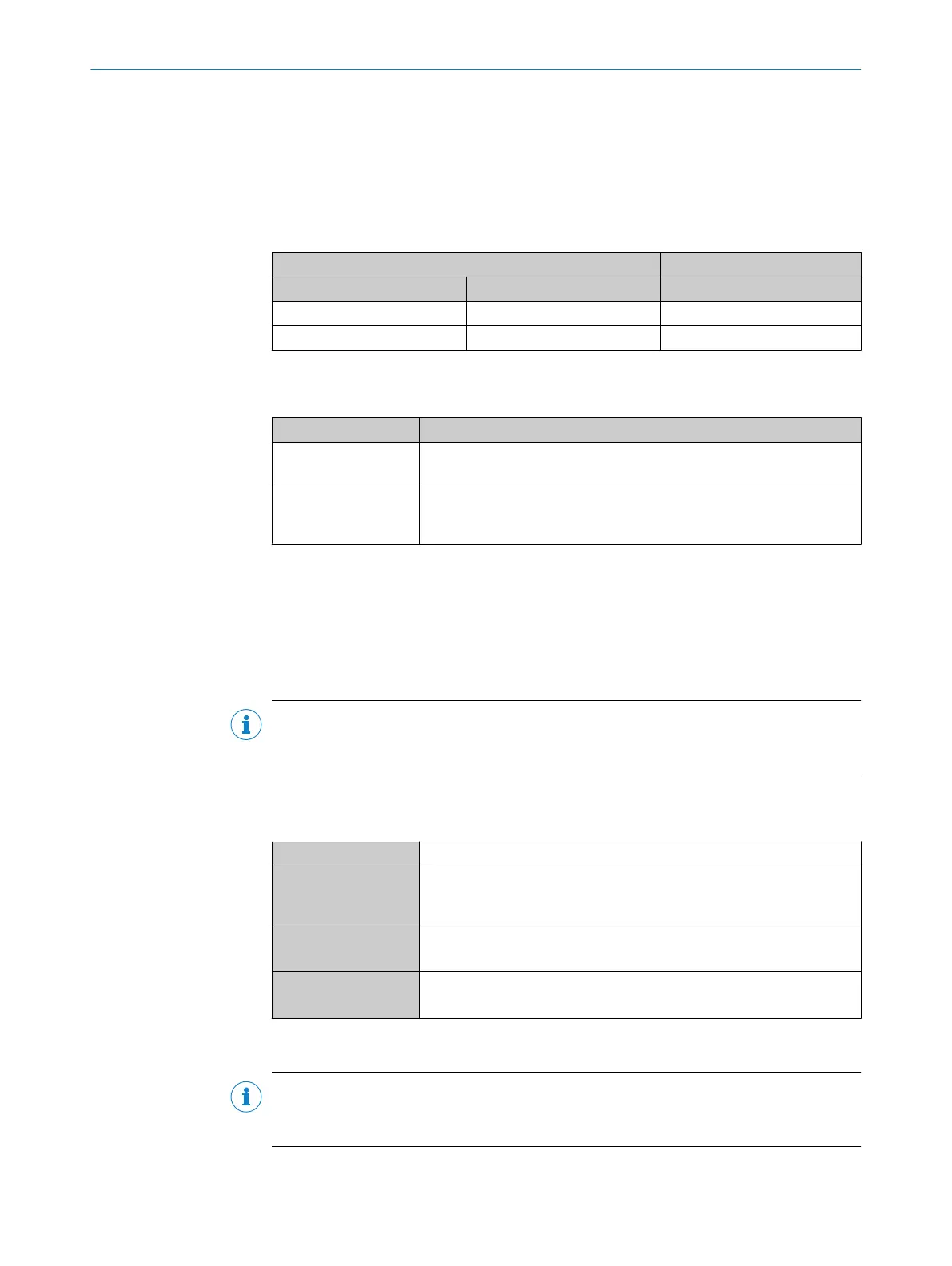
Table 72: Assignment of placeholders to the digital inputs
CDM420-0001 Device
Terminal A Signal B External input C
18 Aux In 1 1
19 Aux In 2 2
Function of switch S6
Table 73: Switch S6: SGND - GND
Switch setting Function
ON GND of the trigger sensor connected with GND of CDM420-0001 and
CMC600
OFF Trigger sensor connected potential-free at CDM420-0001 and
CMC600.
Common, isolated reference potential of all digital inputs is SGND.
Functional principle of the external digital inputs
As a software-controlled operation, the CMC600 automatically transmits the output
states of its physical digital inputs “Aux In 1” and “Aux In 2” in the connection module
via the connecting cable to the serial Aux interface of the device. The device imple‐
ments the states internally on its logical inputs “External input 1” and “External
input 2”.
NOTE
The external digital inputs are software-defined. This results in a delay of maximum
15 ms when transmitting the signal input at the CMC600 to the device.
Characteristic data of the digital inputs
Table 74: Characteristic data of the digital inputs “External input 1” and “External input 2”
Type Switching
Switching behavior Power to the input starts the assigned function, e.g. start read cycle.
Default setting in the device: logic not inverted (active high), debounce
time 10 ms
Properties
•
Opto-decoupled, reverse polarity protected
•
Can be wired with PNP output of a trigger sensor
Electrical values Low: V
in
1)
≤ 2 V; I
in
2)
≤ 0.3 mA
High: 6 V ≤ V
in
≤ 30 V; 0.7 mA ≤ I
in
≤ 5 mA
1)
Input Voltage
2)
Input current
NOTE
Assign the functions for the external digital inputs in the device using a configuration
tool, e.g., the SOPAS ET configuration software.
13.7.9 Wiring the digital outputs “Result 1” and “Result 2” of the device in the CDM420-0001
13 ANNEX
126
O P E R A T I N G I N S T R U C T I O N S | Lector621 8022502/15NT/2020-02-11 | SICK
Subject to change without notice