Preventive Maintenance
28 MCS100E HW Maintenance Manual 8009624/2009-09 (V1.4) ©SICKMAIHAKGmbH
3 Add a little bit of adhesive onto the thread of the pressure disk.
4 Tighten the pressure disk firmly with the tool for pressure disk - again retaining the con-
rod.
5 Fit the intermediate plate
– According to line marking
OR
– The cutout for the valve plate must point to the top (according to
→
Fig. 27).
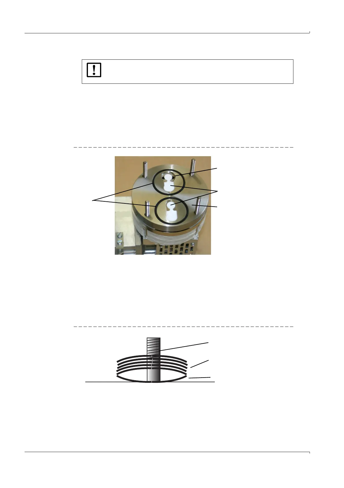
6 Fit the o-rings and the valve plates.
Fig. 27 O-rings, valve plates
7 Fit the pump head.
– According to line marking
OR
– The cut out in the pump head must be across from the cut out of the intermediate
plate.
The direction of the gas flow is indicated by the directional arrows on the pump head
(
→
Fig. 29).
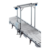
8 Fit the cup springs (6 pcs.).
Fig. 28 Cup springs, position
Fit the bottom cup spring with the concave side pointing upwards.
Fit the remaining 5 cup springs with the concave sides pointing downwards.
Notice:
Really use only very little of the adhesive, otherwise the screw probably
can’t be unscrewed again.
Valve plates
Intermediate plate
O-rings
Cut out
Threaded bolt
5 cup springs
Bottom cup spring