Preventive Maintenance
32 MCS100E HW Maintenance Manual 8009624/2009-09 (V1.4) ©SICKMAIHAKGmbH
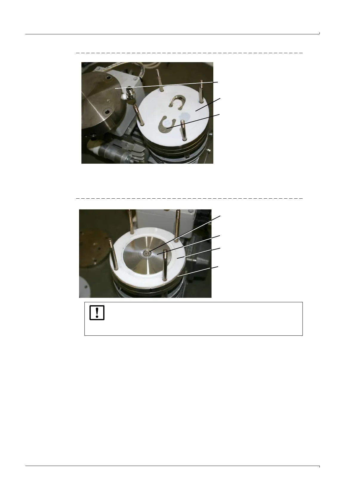
Fig. 34 Pump head, valve plate, intermediate plate
6 Remove the valve plate.
7 Remove the intermediate plate.
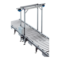
8 Unscrew the countersunk screw.
Fig. 35 Countersunk screw, pump membrane, pressure disk, lower pressure plate
Pump head
Valve plate
Intermediate plate (hidden)
The countersunk screw has a very tight seat.
b
Only use a well fitting 4 mm Allen key.
b
Heat the Allen key to the temperature of the pressure disk.
Otherwise you will severely damage the hexagon in the screw head.
Countersunk screw
Pressure disk
Pump membranes
Lower pressure plate (hidden)