•
Ident
ification (UDInt, Little Endian): Datagrams (fragments), which belong to the
same instance of the data output, have the same value. The value is increased for
every instance of data output in one channel.
•
Fragment offset (UDInt, Little Endian): Offset (in bytes) of the measurement data
in datagram (fragment) compared to the start of the instance of the data output.
Due to the additional header, the actual fragment of the data output begins at offset 24
in the data field of the UDP datagram. In the following example of a complete UDP data‐
gram, the L2 Ethernet frame, the IPv4 and the UDP headers are marked in red. The
additional, 24 byte-long header is marked in blue. The following data marked in green is
the actual measurement data or a fragment of it.
Table 2: Example: UDP datagram
0000 00 e1 11 00 30 20 00 06 77 ff 08 ae 08 00 45 00 ....0 ..w.....E.
0010 05 d0 69 37 00 00 40 11 89 b9 c0 a8 00 aa c0 a8 ..i7..@.........
0020 00 32 c3 50 c3 50 05 bc e5 cb 4d 53 33 20 4d 44 .2.P.P....MS3 MD
0030 01 00 b8 0c 00 00 4b 01 00 00 00 00 00 00 00 00 ......K.........
0040 00 00 52 02 00 00 6d b5 0a 01 8c 8f 0a 01 00 00 ..R...m.........
0050 00 00 4b 01 00 00 b4 5b 00 00 00 00 00 00 24 99 ..K....[......$.
0060 0a 00 4c 00 10 00 60 00 18 00 7c 00 68 08 e8 08 ..L...`...|.h...
0070 80 02 6c 0b 08 01 78 0c 40 00 00 00 00 00 00 00 ..l...x.@.......
0080 00 00 00 00 00 00 00 00 00 00 01 00 00 00 01 55 ...............U
4.5 Configured and actually used angular range
When configuring the data output, you enter a start angle and an end angle. The actu‐
all
y used angles can deviate slightly from the configured angles.
The actually used angular range always contains the entire configured angular range.
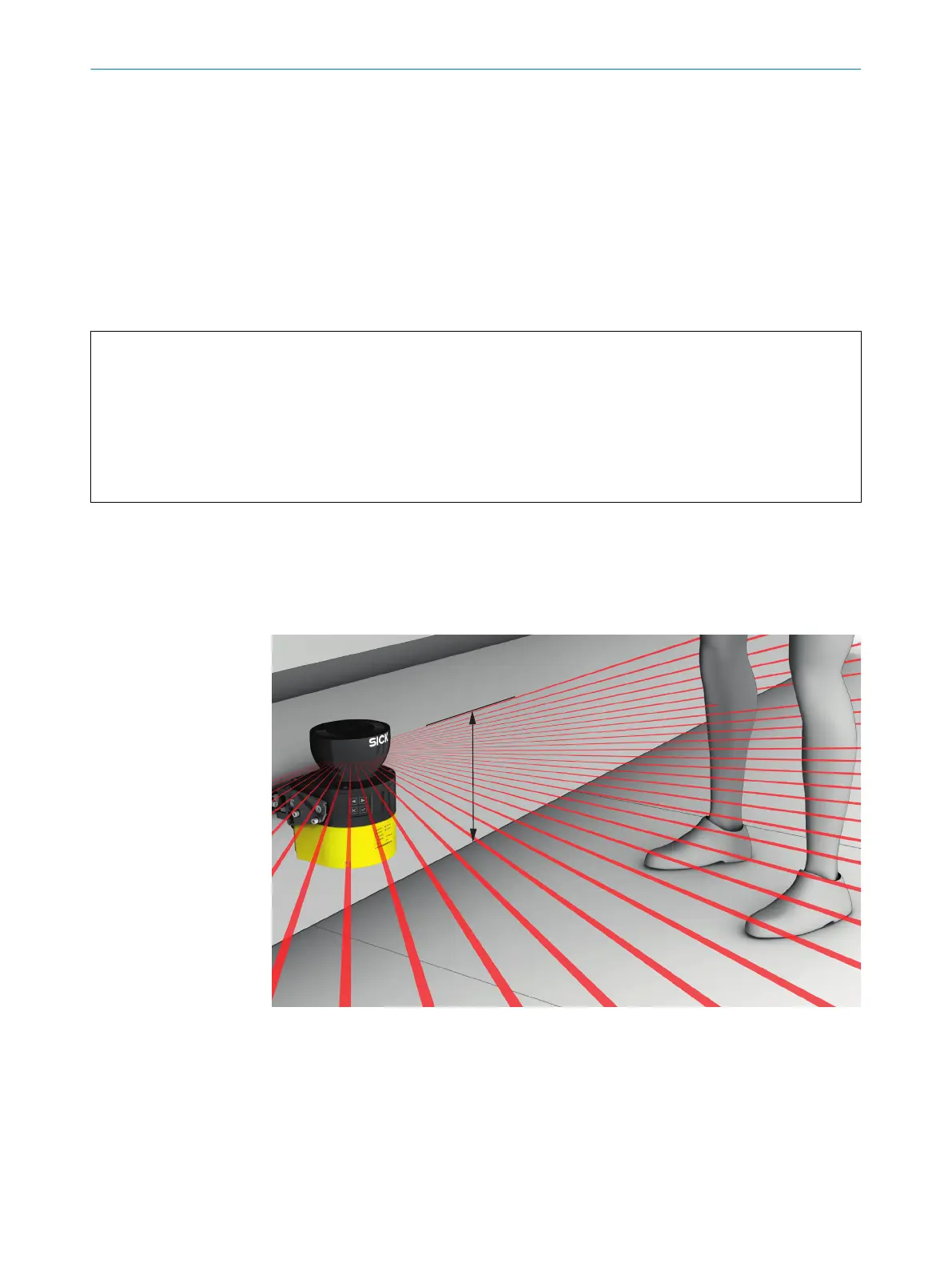
Figure 6: Laser beams
E
very laser beam of the safety laser scanner is emitted in a defined angle. Measure‐
ment data is only available for the angles in which a laser beam is emitted.
Field interruptions are not evaluated for each individual laser beam, rather for every 8th
beam.
Therefore the start angle and the end angle are rounded down (start angle) or rounded
up (end angle) to the next laser beam that has a number that is a multiple of 8.
DATA OUTPUT 4
8022708/2019-04-15 | SICK T E C H N I C A L I N F O R M A T I O N | microScan3, outdoorScan3
15
Subject to change without notice