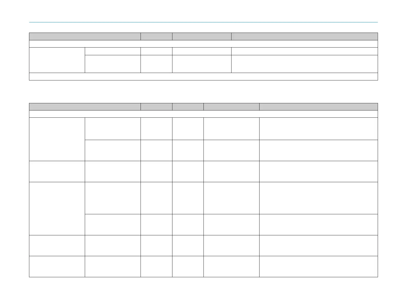
Structure Data type Length in bytes Description
~ ~ ~
Field interruption
1)
Length UDInt 4
Number of bytes in the data field Flags.
Flags SCont [Length] One bit for each beam in the configured angular range.
0: Be
am not interrupted
2)
1: Beam interrupted
2)
~ ~ ~
1)
One data field per cut-off path. The data field is repeated 24 times.
2)
Only the bits are 1 whose beams are interrupted by an object and the switch the cut-off path into the OFF state.
Table 6: Block application data (inputs)
Structure Data type Length in bytes Offset in bytes Description
~ ~ ~
Static control inputs Control input DCont 4
Offset (Block
application data)
+ 0
UDInt value. Each bit represents the logical status of a static con‐
t
rol inputs.
For complementary evaluation, the static control inputs are evalu‐
ated in pairs.
Flags DCont 4
Offset (Block
application data)
+ 4
Flags: Each bit stands for a static control input. If the bit has the
v
alue 1, the static control input is available for monitoring case
switchover.
Reserved 4
Offset (Block
application data)
+ 8
Monitoring case numbers Monitoring case number
(monit
oring case table n)
Array of 20 ×
UInt
40
Offset (Block
application data)
+ 12
Only if the monitoring case numbers are used for the monitoring
c
ase switchover (e.g. assembly 103): each element of the array
stands for the monitoring case number of a monitoring case table.
The safety laser scanner currently only supports one monitoring
case table. Therefore only the first element of the array is currently
used.
Flags DCont 4
Offset (Block
application data)
+ 52
The monitoring case number of the corresponding monitoring case
t
able is available for the monitoring case switchover
Reserved 6
Offset (Block
application data)
+ 56
Reserved 2
Offset (Block
application data)
+ 62
ANNEX 7
8022708/2019-04-15 | SICK T E C H N I C A L I N F O R M A T I O N | microScan3, outdoorScan3
25
Subject to change without notice