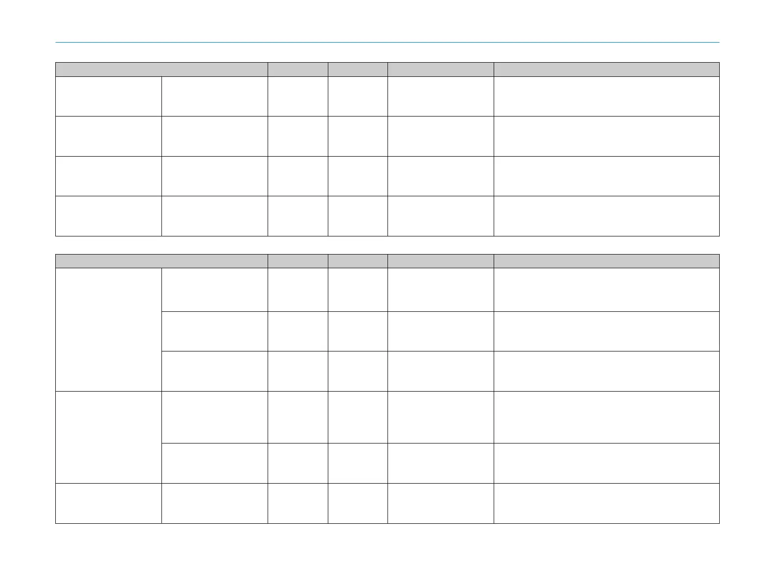
Structure Data type Length in bytes Offset in bytes Description
Reserved 10
Offset (Block
application data)
+ 64
Standby state input Enum8 1
Offset (Block
application data)
+ 74
1 = Standby state input is HIGH.
2 = St
andby state input is LOW.
Reserved 1
Offset (Block
application data)
+ 75
Reserved 64
Offset (Block
application data)
+ 76
Table 7: Block application data (outputs)
Structure Data type Length in bytes Offset in bytes Description
Cut-off paths Cut-off path DCont 4
Offset (Block
application data)
+ 140
Bits 0 – 19: logic status of the non-secure cut-off path.
Bit
s 20 … 31: Reserved
The bit position of a cut-off path corresponds to its number in the
assembly or process image that was defined in Safety Designer.
Safe DCont 4
Offset (Block
application data)
+ 144
The respective cut-off path is safe.
Valid DCont 4
Offset (Block
application data)
+ 148
The bit of the corresponding cut-off path is valid.
Monitoring case number Monitoring case number
(monit
oring case table n)
Array of 20 ×
UInt
40
Offset (Block
application data)
+ 152
Each element of the array represents for the number of the active
monit
oring case of a monitoring case table.
The safety laser scanner currently only supports one monitoring
case table. Therefore only the first element of the array is currently
used.
Flags DCont 4
Offset (Block
application data)
+ 192
The monitoring case number of the corresponding monitoring case
t
able is valid.
Status standby state Enum8 1
Offset (Block
application data)
+ 196
1: Device in standby
2: D
evice not in standby
7 ANNE
X
26
T E C H N I C A L I N F O R M A T I O N | microScan3, outdoorScan3 8022708/2019-04-15 | SICK
Subject to change without notice