y y
xx
y y
xx
1
2
3
1
2
4
m
m
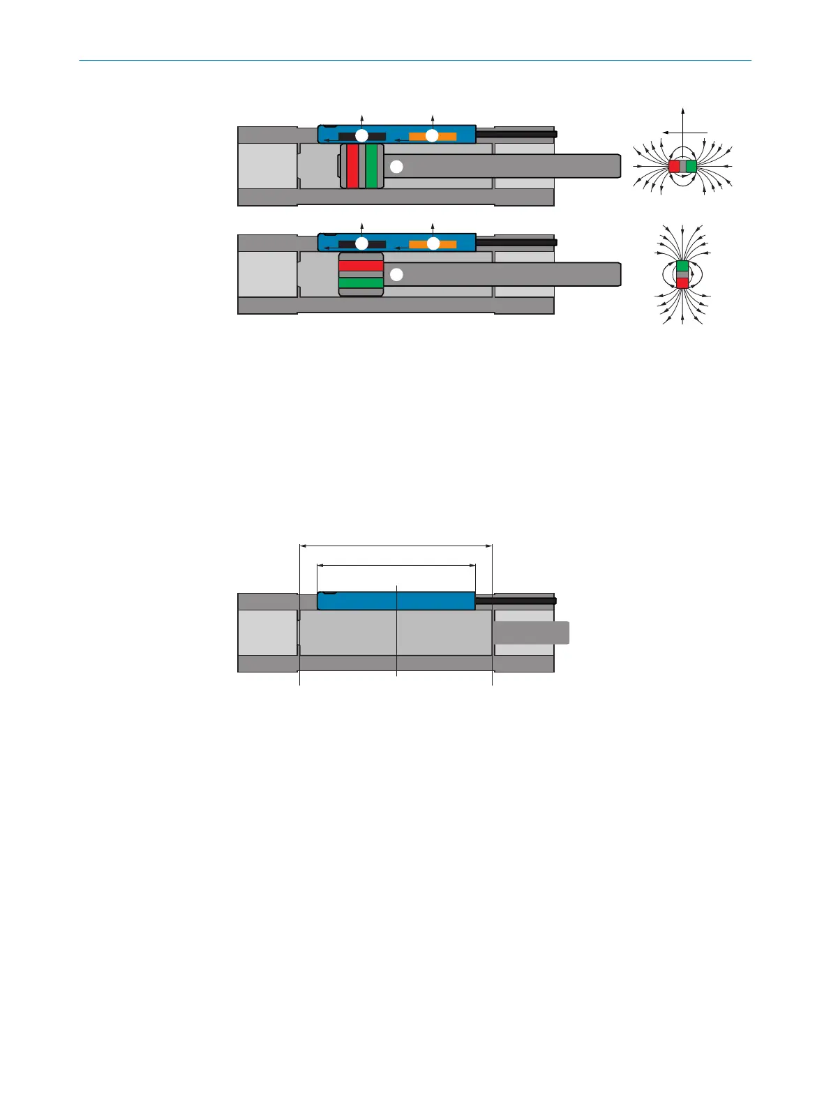
y (radial)
x (axial)
1
Sensor element 1
2
Sensor element 2
3
Axially magnetized magnet
4
Diametrically magnetized magnet
3.3.2 Detection range
The sensor is designed for a detection range of 50mm. The zero point / physical
zero position is marked with arrows on the sensor head and is located roughly at the
center point of the sensor. From the zero point, -25mm are measured to the cable and
+25mm to the fixing screw.
50 (1.97)
25.3 (1.00)
0
- 25 (0.98)+ 25 (0.98)
1
2
3
Figure 3: Detection range
1
Detection range
2
Housing length
3
Zero point / physical zero position
3.3.3 Position output
The sensor can output a linearized position in a detection range of approx. 50mm
(depends on the drive).
Via IO-Link, the detection range of 50mm (-25mm ... 25mm) corresponds to 5,000
digits (-2,500digits ... 2,500digits). I.e. 1 digit corresponds to 10µm.
When leaving the detection range, the value 32,760 or -32,760 digits
1)
is displayed.
If the field strength is no longer sufficient, 32764 is output as per the Smart Sensor
profile.
1)
1digit corresponds to 10µm.
3 PRODUCT DESCRIPTION
10
O P E R A T I N G I N S T R U C T I O N S | MPS-G with 2/3 switching points and IO-Link (up to 8 switching points) 8028195/2022-11-30 | SICK
Subject to change without notice