A description of the diagnostic functions can be found in section 8.4.4.
Target application
•
Double end position detection via 2 digital switching points
→ Substitute for two individual cylinder switches
•
Detection of 3 positions via 3 digital switching points, e.g. for gripper process
(open without object / object gripped / closed without object)
→ Substitute for three individual cylinder switches
•
Position measurement for short stroke in systems with IO-Link
•
Detection of 8 positions via 8 switching points, e.g. for gripper process (gripping of
objects of different sizes)
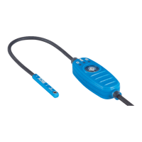
Mechanical standard variants
The mechanical standard variants differ in the geometry of the sensor head, the length
of the connection cable between the head and control panel, the length of the connect‐
ing cable between the control panel and connection and in the connection.
Figure 2: MPS-G structure
1
Sensor head:
Festo slot (F)
SMC slot (S)
2
Head / Control panel connection cable
3
Sensor connecting cable
4
Sensor connection
Table 1: Mechanical variants
Part number Type desig‐
nation
Sensor
head
Connec‐
tion
cable
Functional scope
(output)
Connecting cable
1127842 MPS-G50 ... F 0.1m 2/3Q and IO-Link 0.5m, M8 knurled screw
1127843 MPS-G50 ... S 0.1m 2/3Q and IO-Link 0.5m, M8 knurled screw
1127844 MPS-G50 ... S 0.5m 2/3Q and IO-Link 0.5m, M8 knurled screw
1127845 MPS-G50 ... F 0.1m 2/3Q and IO-Link 0.3m, M12
1127846 MPS-G50 ... S 0.1m 2/3Q and IO-Link 0.3m, M12
1127847 MPS-G50 ... S 0.5m 2/3Q and IO-Link 0.3m, M12
3.3 Operating principle
3.3.1 Principle of operation
The MPS-G determines the position of an encoder magnet via a row of 2 sensor
elements located in the sensor head.
Axially and diametrically magnetized magnets can be detected since the two sensor
elements measure the field strength in both the X- and Y-direction.
PRODUCT DESCRIPTION 3
8028195/2022-11-30 | SICK O P E R A T I N G I N S T R U C T I O N S | MPS-G with 2/3 switching points and IO-Link (up to 8 switching points)
9
Subject to change without notice
 Loading...


