5 Mounting
5.1 Mounting requirements
■
Comply with technical data such as the permitted ambient conditions for operation
of the sensor (e.g., temperature range, EM interference), see "technical data",
page 51.
■
Protect the sensor from direct sunlight.
■
Only mount sensor with the intended accessories.
Mounting location
When selecting the mounting location, the following factors must be considered:
■
The mounting location must be as free from (electro)magnetic disturbance fields
as possible
5.2 Optional accessories
Table 5: Optional accessories
Part number Designation
2117133 Control panel mounting
2117770 T-slot adapter
5.3 Mounting
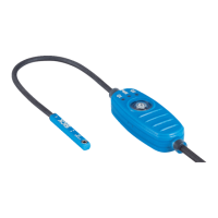
Insert sensor into the slot from above. The PWR LED
2)
lights up green .
Figure 14: Installation steps
1
Insert sensor
2
Turn sensor
3
Tighten screws (tightening torque max. 0.1Nm)
NOTE
When tightening the screw, use a non-magnetic Allen key.
2)
PWR LED = Power LED
MOUNTING 5
8028195/2022-11-30 | SICK O P E R A T I N G I N S T R U C T I O N S | MPS-G with 2/3 switching points and IO-Link (up to 8 switching points)
21
Subject to change without notice
 Loading...
