8 Operation
8.1 General notes on operation
Teach-in can be performed using the teach-in button or IO-Link.
NOTE
The user is responsible for the correct teach-in procedure.
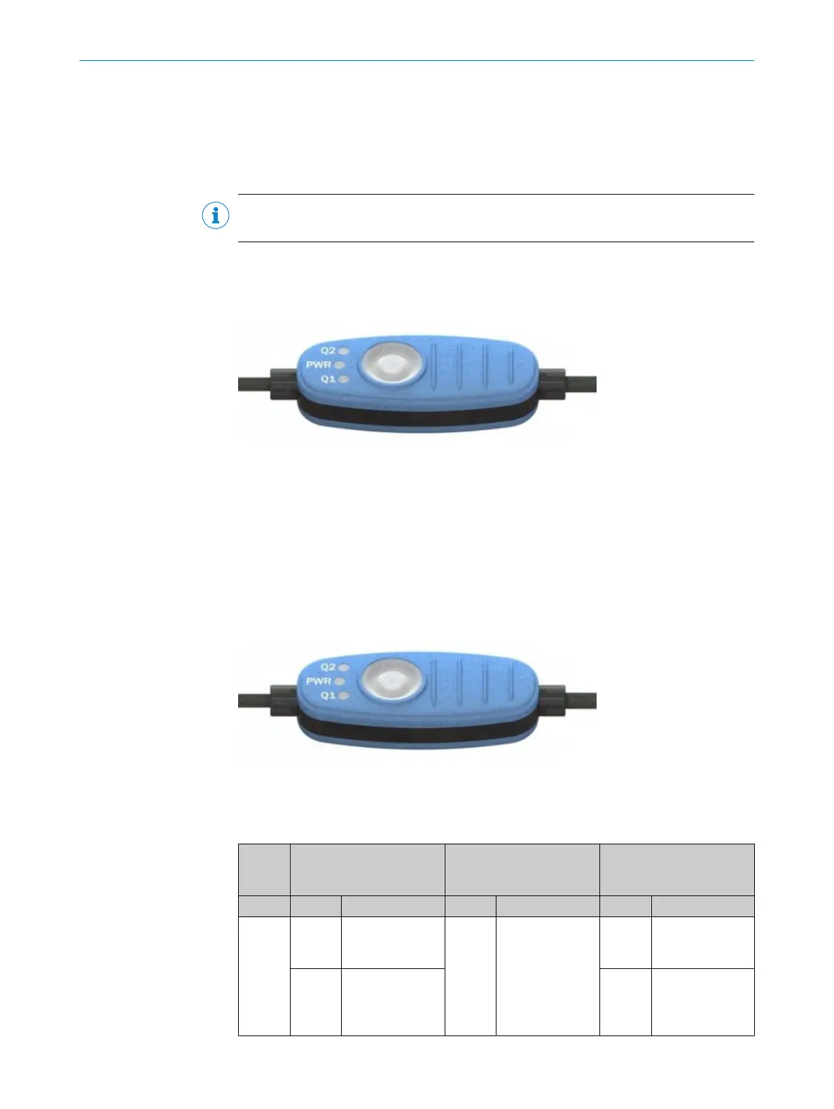
8.2 Operating and status indicators
8.2.1 Control element
The following settings can be made via the teach-in button.
•
Definition of up to 3 switching points (digital outputs) via Dynamic Teach function
•
Manual definition of 1 to 3 switching points (digital outputs)
•
Adjustment of overrun distance per switching point (1 – 5mm) (after Manual Teach)
•
Deactivation of all switching points
8.2.2 Status indicators
3 LEDs are arranged on the control panel. The two outer LEDs light up yellow and the
center LED in green.
The table below describes the individual function displays. The actual behavior of the
LEDs during operation represents a combination of these function displays.
Table 9: Function of the LEDs
Sensor
condi‐
tion
LED 1 (Q1) LED 2 (PWR) LED 3 (Q2)
Display Meaning Display Meaning Display Meaning
SIO
1
O
Lights
up
Q1 high
O
Lights
up
Power ok
O
Lights
up
Q2 high
o
Does
not light
up
Q1 low
o
Does
not light
up
Q2 low
8 OPERATION
28
O P E R A T I N G I N S T R U C T I O N S | MPS-G with 2/3 switching points and IO-Link (up to 8 switching points) 8028195/2022-11-30 | SICK
Subject to change without notice