Bitoffset
Byte 0 / Descrip‐
tion
31 /
Meas‐
ure‐
ment
value
30 /
Meas‐
ure‐
ment
value
29 /
Meas‐
ure‐
ment
value
28 /
Meas‐
ure‐
ment
value
27 /
Meas‐
ure‐
ment
value
26 /
Meas‐
ure‐
ment
value
25 /
Meas‐
ure‐
ment
value
24 /
Meas‐
ure‐
ment
value
Subindex
Data Type Integer 16
Bitoffset 16
Byte 1 / Descrip‐
tion
23 /
Meas‐
ure‐
ment
value
22 /
Meas‐
ure‐
ment
value
21 /
Meas‐
ure‐
ment
value
20 /
Meas‐
ure‐
ment
value
19 /
Meas‐
ure‐
ment
value
18 /
Meas‐
ure‐
ment
value
17 /
Meas‐
ure‐
ment
value
16 /
Meas‐
ure‐
ment
value
Subindex 1
Data Type Integer 16
Bitoffset 8
Byte 2 / Descrip‐
tion
15 /
Scale
14 /
Scale
13 /
Scale
12 /
Scale
11 /
Scale
10 /
Scale
9 /
Scale
8 /
Scale
Subindex 2
Data Type Integer 8
Bitoffset 7 6 5 4 3 2 1 0
Byte 3 / Descrip‐
tion
7 /
QIntX/
Alert
6 /
QIntX/
Alert
5 /
QIntX/
Alert
4 /
QIntX/
Alert
3 /
QIntX/
Alert
2 /
QIntX/
Alert
1 /
QIntX/
Alert
0 /
QIntX/
Alert
Subindex 3 4 5 6 7 8 9 10
Data Type Boolean
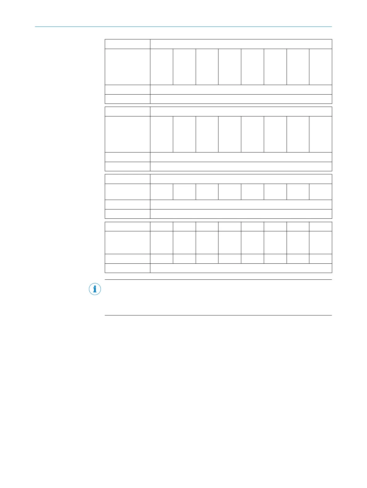
NOTE
Please note that the value of index 16512 MDC Descr, subindex 1 and 2 (Measurement
Range) may change during operation of the sensor (while the sensor is being taught in
for the drive).
8.4.2 General functions
The exact position is output in mm from -25mm to +25mm via byte1 and 0bit 16 to
31 of the process data. The scaling is specified by the sensor via byte2 and up to 8
switching points can also be output via byte 3. Alternatively, alert notifications can be
output via byte3 instead of switching points.
For details, see section 8.4.3.6.
8.4.3 Configuration options via IO-Link
The following settings can be configured using IO-Link:
•
Pin 2 configuration (output)
•
Lock teach-in button
•
Reset
°
Device Reset
°
Restore Factory Settings
°
Reset diagnostic parameters
°
Reset all present alerts
OPERATION 8
8028195/2022-11-30 | SICK O P E R A T I N G I N S T R U C T I O N S | MPS-G with 2/3 switching points and IO-Link (up to 8 switching points)
37
Subject to change without notice