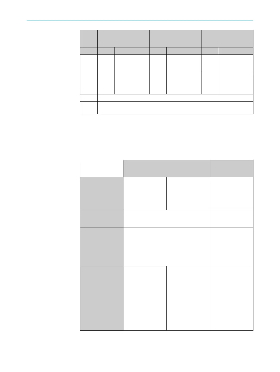
Sensor
condi‐
tion
LED 1 (Q1) LED 2 (PWR) LED 3 (Q2)
Display Meaning Display Meaning Display Meaning
IO-Link
2
O
Lights
up
Q1 high
F
Flash‐
ing
IO-Link active
O
Lights
up
Q2 high
o
Does
not light
up
Q1 low
o
Does
not light
up
Q2 low
Error No error display via LEDs
Teach
This table only lists the LED behavior during operation.
The LED behavior during teach-in can be found in section 8.3.
1
If LED 1 (Q1), LED 2 (PWR) and LED 3 (Q3) light up at the same time, Q3 is active.
2
•
During position measurement via IO-Link, only LED 2 (PWR) flashes
•
Up to 16 switching points can be taught in via IO-Link. Only the first 3 switching points are shown
via LEDs as in SIO mode.
8.3 Teach-in mode
Table 10: Teach-in procedure
Teach-in mode Dynamic Teach-in
Automatic teach-in of the switching points
Manual Teach-in
Manual teach-in of
the switching points
Number of switching
points
2 switching points
When 2 x speed v
1
=
0 is detected during
teach-in.
3 switching points
When 3 x speed v
1
=
0 is detected during
teach-in.
3 switching points
Between 1 and 3
switching point (Qints)
can be manually
taught in independ‐
ently of each other.
Are switching points
(SP) taught in inde‐
pendently?
NO
Depending on the requirement, 2 or 3 Qints
can be taught in one process.
YES
Up to 3 SP are taught
in independently.
Is Dynamic Pilot active? YES
In Dynamic Pilot, there are 2 conditions for Qint
during operation
ON: The piston velocity must be v = 0
1
. The
magnet must be within the tolerance band
defined in Dynamic Teach and the direction of
movement of the piston must correspond.
NO
If the switching points
are taught in man‐
ually, there is no
Dynamic Pilot.
Arrangement of
switching points
Always the same
Qint1 lies in the direc‐
tion of the cable outlet
and Qint2 in the direc‐
tion of the sensor fix‐
ing screw
Depends
The switching points
are assigned as fol‐
lows:
Qint1 = idle
Qint2 = object
Qint3 = noobject
That is why the
arrangement depends
on whether an internal
or external gripper is
used.
Free arrangement
The Qint1, Qint2 and
Qint3 switching points
can be freely set.
OPERATION 8
8028195/2022-11-30 | SICK O P E R A T I N G I N S T R U C T I O N S | MPS-G with 2/3 switching points and IO-Link (up to 8 switching points)
29
Subject to change without notice