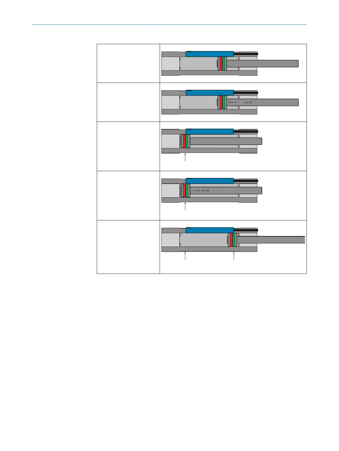
Table 2: Switching behavior with 2 switching points
1.) Output position v= 0.
No switching point is
defined at the output posi‐
tion of the magnet.
2.) Movement in the direc‐
tion of the sensor fixing
screw
3.) First stop: First posi‐
tion is defined for switching
point
4.) Movement in the direc‐
tion of the cable side
5.) Second stop: Second
position for switching point
and arrangement of Qint2
(see fixing screw) and
Qint1 (cable set) are
defined
1. Stop:
Qint 2
2. Stop:
Qint 1
v = 0
Switching behavior after Dynamic Teach of 2 switching points is the following during
operation:
PRODUCT DESCRIPTION
3
8028195/2022-11-30 | SICK O P E R A T I N G I N S T R U C T I O N S | MPS-G with 2/3 switching points and IO-Link (up to 8 switching points)
13
Subject to change without notice