125
GB
MSL coded version
8 007 898/O369/05-04-04 Operating instruction • MSL cod. © SICK AG • Industrial Safety Systems • Germany • All rights reserved
2 General safety instructions
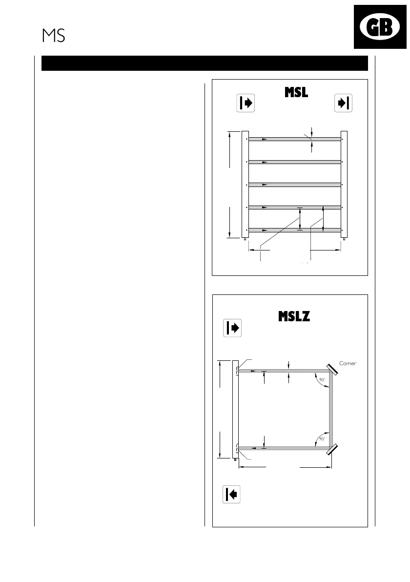
The MSL multibeam photoelectric safety
switch consists of two components: the
sender unit MSLS and the receiver unit
MSLE (
top diagram
). Between the two
units, the individual beams of light create
a protective field defined by the number
of beams and their spacing. The position
of the light beam is indicated by a
marking on the housing.
On the MSLZ the sender and receiver
units are in one housing (column) -
bottom diagram
.
If an object interrupts at least one beam
of light (manual intervention or me-
chanical obstacle) the receiver unit
sends a Stop signal to the machine or
plant. This prevents the machinery from
starting or stops a hazardous movement.
The device can only perform its safety
function if it is correctly connected and
mounted.
MSLZ
Strahlabstand
Gehäuselänge
Sende-
element
Empfangs-
element
Lichtstrahl-
durchmesser 23 mm
90˚
90˚
Umlenkspiegel
Umlenkspiegel
max. 7,5 m
Corner
mirrors
Corner
mirrors
Light beam
Sender
element
Housing length
Beam gap 500 mm
Receiver element
Operating
range max.
7,5 m
MSL
Gehäuselänge
Reichweite
Strahlabstand
Sende-
einheit
Empfangs-
einheit
Lichtstrahl-
durchmesser
23 mm
Auflösung
ReceiverSender
Housing length
Operating range
Light beam
diameter
23 mm
Beam gap
Resolution
241967_MSLcv_GB_3.p65 10.12.04, 09:40125
Schwarz
 Loading...


